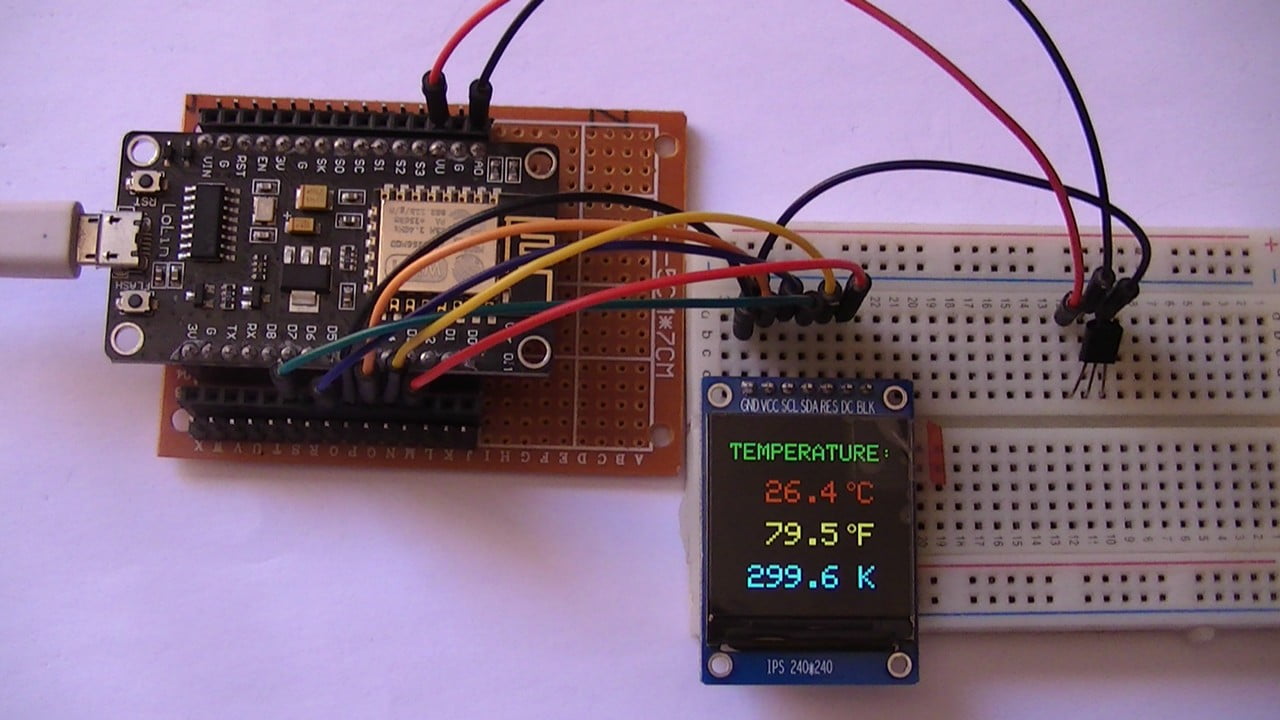
This project shows how to interface ESP8266 NodeMCU board with ST7789 SPI TFT display and LM35 analog temperature sensor.
The values of temperature are printed on the ST7789 TFT in degrees Celsius, degrees Fahrenheit and Kelvin.
The ST7789 TFT module contains a display controller with the same name: ST7789. It’s a color display that uses SPI interface protocol and requires 3, 4 or 5 control pins, it’s low cost and easy to use. This display is an IPS display, it comes in different sizes (1.3″, 1.54″ …) but all of them should have the same resolution of 240×240 pixel, this means it has 57600 pixels. This module works with 3.3V only and it does not support 5V.
TFT: Thin-Film Transistor.
SPI: Serial Peripheral Interface.
IPS: In-Plane Switching.
To see how to interface the ESP8266 NodeMCU board with ST7789 TFT display, visit this post:
Interfacing ESP8266 NodeMCU with ST7789 TFT Display
About the LM35 sensor:
The LM35 temperature sensor is a three pin device (VCC, OUT and GND) with an output voltage linearly related to Centigrade temperature. Since the LM35 output varies with dependent to the temperature, we need an ADC (Analog-to-Digital Converter) module to measure this voltage. The NodeMCU microcontroller (ESP8266EX) has one ADC module with 10-bit resolution.
The LM35 output has linear +10mV/°C scale factor means the following:
If the output voltage = 10mV —> temperature = 1°C
If the output voltage = 100mV —> temperature = 10°C
If the output voltage = 200mV —> temperature = 20°C
If the output voltage = 370mV —> temperature = 37°C
and so on.
LM35 Futures (from datasheet):
- Calibrated Directly in ° Celsius (Centigrade)
- Linear + 10 mV/°C Scale Factor
- 0.5°C Ensured Accuracy (at +25°C)
- Rated for Full −55°C to +150°C Range
- Suitable for Remote Applications
- Low Cost Due to Wafer-Level Trimming
- Operates from 4 to 30 V
- Less than 60-μA Current Drain
- Low Self-Heating, 0.08°C in Still Air
- Nonlinearity Only ±¼°C Typical
- Low Impedance Output, 0.1 Ω for 1 mA Load
The ADC module converts analog data into digital data. The ESP8266EX WiFi microcontroller has a 10-bit ADC module with one analog input channel. Negative and positive references of the ADC module are 0V (GND) and 1.0V respectively. This means a 0V is represented by 0 and 1.0V is represented by 1024.
LoLin version of the NodeMCU board analog input is A0 (or ADC0), it’s connected to the ESP8266EX microcontroller through voltage divider of 2 resistors (220k and 100k ohms) as shown in the image below (red circle).
With the built-in voltage divider, the NodeMCU analog channel supports inputs from 0 to 3.3V.
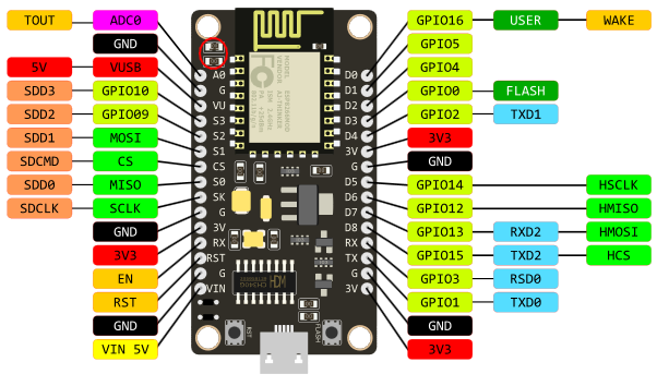
Also, using the LoLin NodeMCU we can supply the LM35 sensor with 5V that comes from pin 5V (VU or VUSB).
Hardware Required:
- ESP8266 NodeMCU board
- ST7789 TFT display module
- LM35 temperature sensor —-> datasheet
- micro USB cable (for programming and powering the circuit)
- Breadboard
- Jumper wires
ESP8266 NodeMCU with LM35 Sensor and ST7789 TFT Circuit:
Project circuit schematic diagram is shown below.
The LM35 sensor has 3 pins (from left to right), it is connected to the ESP8266 NodeMCU board as follows:
Pin 1 is power supply pin, connected to NodeMCU 5V pin (VU),
Pin 2: output pin, connected to NodeMCU pin A0 (ADC0),
Pin 3: GND (ground), connected to NodeMCU GND pin.
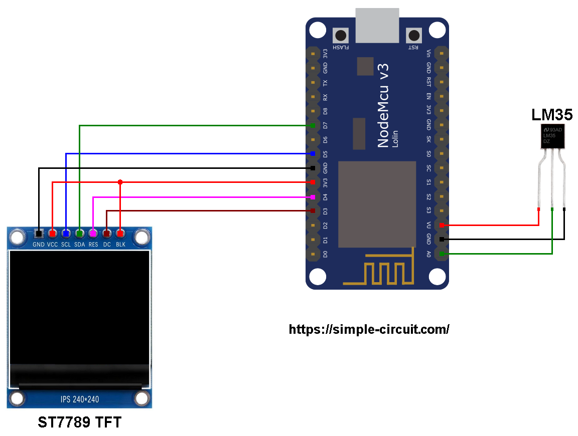
The ST7789 display module shown in project circuit diagram has 7 pins: (from right to left): GND (ground), VCC, SCL (serial clock), SDA (serial data), RES (reset), DC (or D/C: data/command) and BLK (back light).
The ST7789 TFT display module is connected to the NodeMCU board as follows:
GND is connected to pin GND of the NodeMCU board,
VCC and BL are connected to pin 3V3,
SCL pin is connected to D5 (ESP8266EX GPIO14),
SDA pin is connected to D7 (ESP8266EX GPIO13),
RES pin is connected to D4 (ESP8266EX GPIO2),
DC pin is connected to D3 (ESP8266EX GPIO0).
If the display module has a CS pin (Chip Select) then it should be connected to NodeMCU pin D8 (GPIO15).
Connecting the BLK pin is optional. The back light turns off when the BLK pin connected to the ground (GND).
Pins D5 (GPIO14) and D7 (GPIO13) are hardware SPI module pins of the ESP8266EX microcontroller respectively for SCK (serial clock) and MOSI (master-out slave-in).
ESP8266 NodeMCU with LM35 sensor and ST7789 TFT code:
The following Arduino code requires two libraries from Adafruit Industries:
The first library is a driver for the ST7789 TFT display which can be installed from Arduino IDE library manager (Sketch —> Include Library —> Manage Libraries …, in the search box write “st7789” and install the one from Adafruit).
The second library is Adafruit graphics library which can be installed also from Arduino IDE library manager.
The two libraries can be installed manually, first download them from the following links:
Adafruit ST7789 TFT library —-> direct link
Adafruit graphics library —-> direct link
After the download, go to Arduino IDE —> Sketch —> Include Library —> Add .ZIP Library … and browse for the .zip file (previously downloaded).
The same thing for other the 2nd library file.
Hints:
The 2 libraries are included in the main code as follows:
1 2 | #include <Adafruit_GFX.h> // Core graphics library #include <Adafruit_ST7789.h> // Hardware-specific library for ST7789 |
The connection of ST7789 TFT display with the NodeMCU is as shown below where the display is connected to hardware SPI module of the NodeMCU (pins: SCK and MOSI):
1 2 3 4 5 6 7 8 | // ST7789 TFT module connections #define TFT_DC D3 // TFT DC pin is connected to NodeMCU pin D3 (GPIO0) #define TFT_RST D4 // TFT RST pin is connected to NodeMCU pin D4 (GPIO2) #define TFT_CS D8 // TFT CS pin is connected to NodeMCU pin D8 (GPIO15) // initialize ST7789 TFT library with hardware SPI module // SCK (CLK) ---> NodeMCU pin D5 (GPIO14) // MOSI(DIN) ---> NodeMCU pin D7 (GPIO13) Adafruit_ST7789 tft = Adafruit_ST7789(TFT_CS, TFT_DC, TFT_RST); |
And the TFT display is initialized using the following command:
1 2 | // if the display has CS pin try with SPI_MODE0 tft.init(240, 240, SPI_MODE2); // init ST7789 display 240x240 pixel |
Reading analog voltage using ADC module gives a number between 0 and 1023 (10-bit resolution), 0V is represented by 0 and 3.3V is represented by 1023. Converting back the ADC digital value is easy, we can use the following equation:
Voltage (in milliVolts) = ADC_reading * 3300 / 1023
This voltage (in milliVolts) represents the temperature value in tenths degrees Celsius (output value of “273” equals 27.3 °Celsius).
The temperature in tenths Kelvin = (tenth °Celsius) + 2732 (because: K = °C + 273.16).
To get the actual value of each quantity we’ve to divide it by 10. The line below shows an example for temperature in Kelvin:
1 | tft.printf("%03u.%1u K", tKelvin / 10, tKelvin % 10); |
We get the first 3 digits by dividing the tenths value by 10, and the tenths number (number after the decimal point) of the actual temperature value is equal to the reminder of that division (tenths value % 10).
The resolution of this thermometer is about 0.3°C.
Full Arduino code:
1 2 3 4 5 6 7 8 9 10 11 12 13 14 15 16 17 18 19 20 21 22 23 24 25 26 27 28 29 30 31 32 33 34 35 36 37 38 39 40 41 42 43 44 45 46 47 48 49 50 51 52 53 54 55 56 57 58 59 60 61 62 63 64 65 66 67 68 69 70 71 72 73 74 75 76 77 78 79 80 81 82 83 84 85 86 87 | /*********************************************************************** * * NodeMCU Digital thermometer with ST7789 TFT display and LM35 analog * temperature sensor. * This is a free software with NO WARRANTY. * https://simple-circuit.com/ * ***********************************************************************/ #include <Adafruit_GFX.h> // Adafruit core graphics library #include <Adafruit_ST7789.h> // Adafruit hardware-specific library for ST7789 // ST7789 TFT module connections #define TFT_DC D3 // TFT DC pin is connected to NodeMCU pin D3 (GPIO0) #define TFT_RST D4 // TFT RST pin is connected to NodeMCU pin D4 (GPIO2) #define TFT_CS D8 // TFT CS pin is connected to NodeMCU pin D8 (GPIO15) // initialize ST7789 TFT library with hardware SPI module // SCK (CLK) ---> NodeMCU pin D5 (GPIO14) // MOSI(DIN) ---> NodeMCU pin D7 (GPIO13) Adafruit_ST7789 tft = Adafruit_ST7789(TFT_CS, TFT_DC, TFT_RST); void setup(void) { // if the display has CS pin try with SPI_MODE0 tft.init(240, 240, SPI_MODE2); // init ST7789 display 240x240 pixel // if the screen is flipped, remove this command tft.setRotation(2); // fill the screen with black color tft.fillScreen(ST77XX_BLACK); tft.setTextWrap(false); // turn off text wrap option tft.setTextColor(ST77XX_GREEN, ST77XX_BLACK); // set text color to green and black background tft.setTextSize(3); // text size = 3 tft.setCursor(15, 27); // move cursor to position (15, 27) pixel tft.print("TEMPERATURE:"); tft.setTextSize(4); // text size = 4 // print "°C" tft.drawCircle(173, 81, 4, ST77XX_RED); tft.drawCircle(173, 81, 5, ST77XX_RED); tft.setTextColor(ST77XX_RED, ST77XX_BLACK); // set text color to red and black background tft.setCursor(182, 75); tft.print("C"); // print "°F" tft.drawCircle(173, 136, 4, ST77XX_YELLOW); // print degree symbol ( ° ) tft.drawCircle(173, 136, 5, ST77XX_YELLOW); tft.setTextColor(ST77XX_YELLOW, ST77XX_BLACK); // set text color to yellow and black background tft.setCursor(182, 130); tft.print("F"); } // main loop void loop() { // read analog voltage and convert it to tenths °C ( = millivolts) int tCelsius = analogRead(A0) * 3300/1024; int tKelvin = tCelsius + 2732; // convert tenths °C to tenths Kelvin int tFahrenheit = tCelsius * 9/5 + 320 ; // convert tenths °C to tenths °Fahrenheit // print temperature in degrees Celsius tft.setTextColor(ST77XX_RED, ST77XX_BLACK); // set text color to red and black background tft.setCursor(38, 75); if (tCelsius >= 1000) // if temperature >= 100.0 °C tft.printf("%03u.%1u", tCelsius / 10, tCelsius % 10); else tft.printf(" %02u.%1u", tCelsius / 10, tCelsius % 10); // print temperature in degrees Fahrenheit tft.setTextColor(ST77XX_YELLOW, ST77XX_BLACK); // set text color to yellow and black background tft.setCursor(38, 130); if (tFahrenheit >= 1000) // if temperature >= 100.0 °F tft.printf("%03u.%1u", tFahrenheit / 10, tFahrenheit % 10); else tft.printf(" %02u.%1u", tFahrenheit / 10, tFahrenheit % 10); // print temperature in Kelvin tft.setTextColor(ST77XX_CYAN, ST77XX_BLACK); // set text color to cyan and black background tft.setCursor(38, 185); tft.printf("%03u.%1u K", tKelvin/10, tKelvin % 10); delay(1000); // wait a second } // end of code. |
Discover more from Simple Circuit
Subscribe to get the latest posts sent to your email.