The ESP8266 ESP-01 module has 8 pins only of which 4 can be used as I/O (input/output) pins (GPIO0, GPIO2, RX and TX), this number of I/O pins is not enough to run a 16×2 LCD screen which requires at least 6 pins. The solution is to add an I/O expander such as PCF8574 chip (I2C I/O expander). The PCF8574 I/O expander gives us 8 pins from only 2 pins (SDA and SCL) which is more enough for the LCD. This topic shows how to connect the ESP-01 module with I2C LCD provided with PCF8574 chip. This interfacing works also with DFRobot I2C LCD displays.
If you want to see how to use the ESP-01 module for the first time, how to use it with Arduino IDE and how to program (upload sketches) it with Arduino, read the following topic:
ESP8266 WiFi module programming with Arduino UNO board
Hardware Required:
The components listed below are required for this project.
- ESP8266 ESP-01 module
- 16×2 LCD screen
- PCF8574 I/O expander (or PCF8574A) — PCF8574 datasheet
- AMS1117 3V3 voltage regulator
- 10uF capacitor
- 0.1uF (100nF) ceramic capacitor
- 5 x 10k ohm resistor
- 330 ohm resistor
- 10k ohm variable resistor or potentiometer
- 5V source
- Breadboard
- Jumper wires
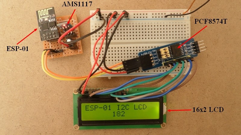
ESP-01 with I2C LCD circuit:
Circuit schematic diagram is shown below.
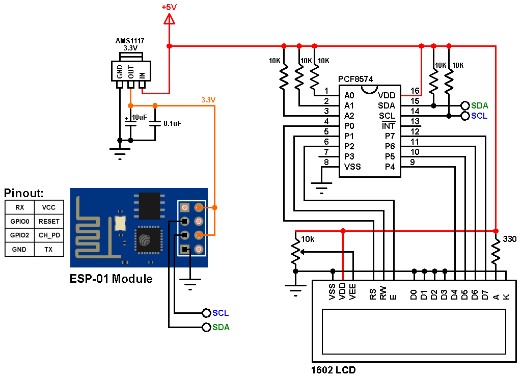
(All grounded terminals are connected together.)
As shown above, the whole circuit needs power source of 5V. The 5V is connected to the LCD screen and the PCF8574 I/O expander VDD pin (#16).
The AMS1117 3V3 regulator is used to feed the ESP-01 module with 3.3V form the 5V source, its role is to convert the 5V into 3.3V, because the operating voltage of the ESP-01 is from 2.5V to 3.6V.
The SDA and SCL lines of the I2C bus come from GPIO0 and GPIO2 of the ESP-01 (respectively), they are connected to PCF8574 SDA pin (#15) and SCL pin (#14). Two pull up resistors of 10k are required for the I2C bus (pulling up the SDA and SCL lines will not do any damage to the ESP8266EX chip).
All LCD data pins are connected to the PCF8574 where: RS, RW, E, D4, D5, D6 and D7 are connected to P0, P1, P2, P4, P5, P6 and P7 respectively.
PCF8574 I/O expander A0, A1 and A2 pins are the address pins, they decide the I2C address of the chip. In this example each pin is connected to +5V through a 10k ohm resistor (the 10k resistor is optional, each pin can be connected directly to +5V).
The I2C address of the PCF8574 is: 0x20 | A2 A1 A0 ( | means OR)
In our circuit A2, A1 and A0 are connected to +5V (through 10k resistors) which means the I2C address is equal to 0x20 | 7 = 0x27
If the PCF8574A is used instead of the PCF8574 the I2C address is: 0x38 | 7 = 0x3F.
The Code:
Project code is below, it’s so simple, we just need a small library for the I2C LCD which works with the ESP-01 module, download links are below, rest of code is described through comments:
LiquidCrystal_I2C Library — direct link
1 2 3 4 5 6 7 8 9 10 11 12 13 14 15 16 17 18 19 20 21 22 23 24 25 26 27 28 29 | // Interfacing ESP8266 (ESP-01) WiFi module with 16x2 I2C LCD #include <Wire.h> // Include Wire library (required for I2C devices) #include <LiquidCrystal_I2C.h> // Include LiquidCrystal_I2C library LiquidCrystal_I2C lcd(0x27, 16, 2); // Configure LiquidCrystal_I2C library with 0x27 address, 16 columns and 2 rows void setup() { lcd.begin(0, 2); // Initialize I2C LCD module (SDA = GPIO0, SCL = GPIO2) lcd.backlight(); // Turn backlight ON lcd.setCursor(0, 0); // Go to column 0, row 0 lcd.print("ESP-01 I2C LCD"); } byte i = 0; char text[4]; void loop() { sprintf(text, "%03u", i++); lcd.setCursor(6, 1); // Go to column 6, row 1 lcd.print(text); delay(500); } |
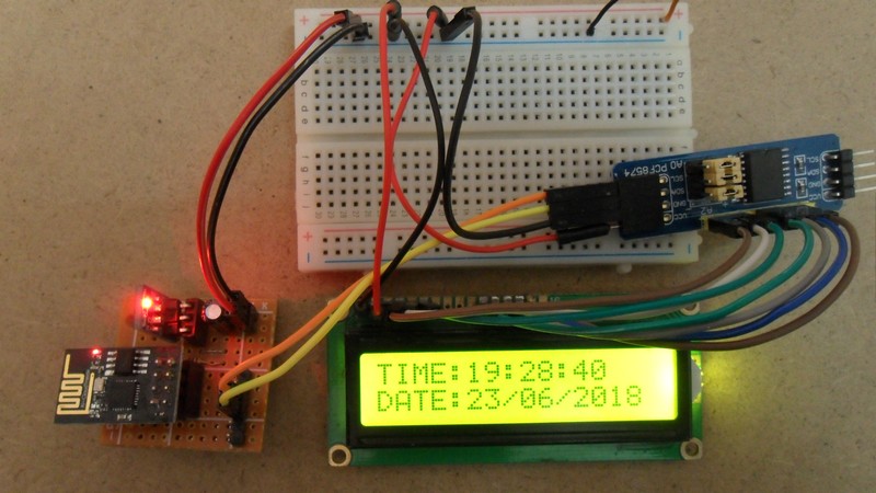
The video below shows my result with hardware circuit:
Discover more from Simple Circuit
Subscribe to get the latest posts sent to your email.

I thought the pins of the ESP01 are not 5V tolerant. However, in this picture, the I²C bus is pulled up to 5V. Shouldn’t one therefore use a level shifter?
Does this verison of liquidcrystal support the Enable 1 and Enable 2 line so therefore use two displays or 1 big 40×4 display?
I have checked with many people on the net on driving the 5V I2C bus on the 3.3V pin of ESP8266-01, it seemed that people are not having a clear affirmation on whether it safe or not for the gpio. Most of them (even NXP) recommended to use level shifter! How about your case? Did you fry your chip after some days of working or they are still survival?
Good job thanks !
lcd.begin(0, 2); does not work. Substituted Wire.begin(0, 2);