Last time I made a simple Arduino datalogger using SD card and DHT11 relative humidity and temperature sensor. Now I’m going to show how to build an Arduino datalogger that logs: date, time, temperature and humidity on an SD card.
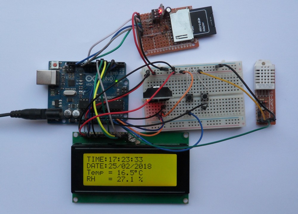
In this project the DS3231 real time clock chip will be used to maintain the time as well as the date and the DHT22 sensor to detect the relative humidity and the temperature. Also, in the circuit there will be two pushbuttons to set up the time and date and a 20×4 LCD screen to display all parameters (time, date, temperature and humidity) as shown below:
Related Projects:
Arduino data logger using SD card and DHT11 sensor
Arduino and DS3231 real time clock
Arduino with DHT22 sensor and LCD
Components Required:
- Arduino board —> ATmega328P datasheet
- DS3231 board —> DS3231 datasheet
- DHT22 relative humidity and temperature sensor —> datasheet
- 20×4 (2004) LCD screen
- SD card
- SD card socket (connector)
- 2 x push button
- 2 x 10K ohm resistor
- 4.7K ohm resistor
- 3 x 3.3K ohm resistor
- 3 x 2.2K ohm resistor
- 330 ohm resistor
- Breadboard
- Jumper wires
Arduino data logger with SD card, DS3231 and DHT22 sensor circuit:
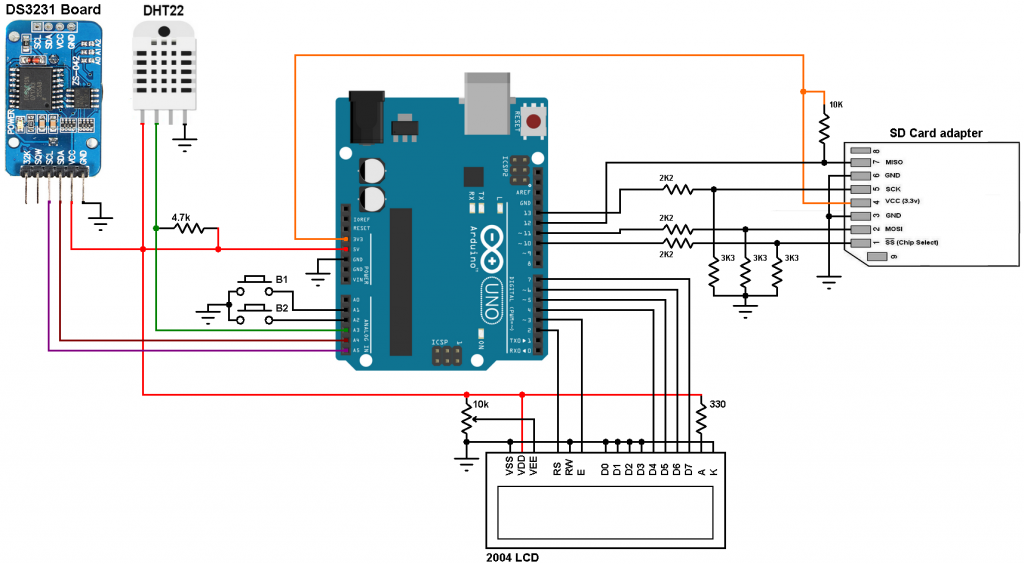
Arduino datalogger circuit diagrams are shown below, both circuits are well working.
The first circuit consists of three voltage dividers to step down the 5V into 3V, the voltage dividers are for: SS (chip select), MOSI (master in slave out) and SCK (serial clock) signals.
(All grounded terminals are connected together)
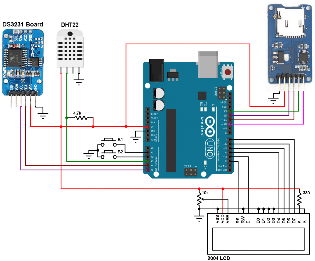
and the second circuit uses micro SD card module, this module is powered with 5V (comes from the Arduino board), it has AMS1117 voltage regulator and a level shifter (74LVC125A) which converts the 5V signals into 3.3V for lines: SS, MOSI and SCK:
(All grounded terminals are connected together)
With the micro SD card module the connections are more simpler, the sd card module is supplied with 5V which comes from the Arduino board.
The SD card module has 6 pins which are (from left to right): GND, VCC, MISO, MOSI, SCK and CS (chip select).
In the circuit there are two push buttons: B1 and B2 connected to Arduino pins A1 and A2 respectively, these buttons are used to set the time and the date of the real time clock.
The DHT22 sensor has 4 pins: VCC, Data, NC (not connected) and GND. It powered with 5V (from the Arduino board).
Arduino data logger with SD card, DS3231 and DHT22 sensor:
The code below reads temperature and humidity from the DHT22 sensor, time and date from the DS3231 chip, then it saves the data into the SD card within a file named Logger.txt and finally it sends the same data serially to PC. The reading and storing of data is done every 1 second.
Full arduino code is below.
1 2 3 4 5 6 7 8 9 10 11 12 13 14 15 16 17 18 19 20 21 22 23 24 25 26 27 28 29 30 31 32 33 34 35 36 37 38 39 40 41 42 43 44 45 46 47 48 49 50 51 52 53 54 55 56 57 58 59 60 61 62 63 64 65 66 67 68 69 70 71 72 73 74 75 76 77 78 79 80 81 82 83 84 85 86 87 88 89 90 91 92 93 94 95 96 97 98 99 100 101 102 103 104 105 106 107 108 109 110 111 112 113 114 115 116 117 118 119 120 121 122 123 124 125 126 127 128 129 130 131 132 133 134 135 136 137 138 139 140 141 142 143 144 145 146 147 148 149 150 151 152 153 154 155 156 157 158 159 160 161 162 163 164 165 166 167 168 169 170 171 172 173 174 175 176 177 178 179 180 181 182 183 184 185 186 187 188 189 190 191 192 193 194 195 196 197 198 199 200 201 202 203 204 205 206 207 208 209 210 211 212 213 214 215 216 217 218 219 220 221 222 | // Real time clock, calendar, temperature, humidity data logger using Arduino, DS3231 and DHT22 sensor // http://simple-circuit.com/ #include <SPI.h> // Include SPI library (needed for the SD card) #include <SD.h> // Include SD library #include <LiquidCrystal.h> // Include LCD library code #include <Wire.h> // Include Wire library code (needed for I2C protocol devices) #include <DHT.h> // Include DHT library code // LCD module connections (RS, E, D4, D5, D6, D7) LiquidCrystal lcd(2, 3, 4, 5, 6, 7); #define B1 A1 // Button B1 is connected to Arduino pin A1 #define B2 A2 // Button B1 is connected to Arduino pin A2 #define DHTPIN A3 // DHT22 data pin is connected to Arduino pin A3 #define DHTTYPE DHT22 // DHT22 sensor is used DHT dht(DHTPIN, DHTTYPE); // Initialize DHT library File dataLog; boolean sd_ok = 0; char temperature[] = " 00.0"; char humidity[] = " 00.0 %"; char Time[] = " : : "; char Calendar[] = " / /20 "; byte i, second, minute, hour, date, month, year, previous_second; int Temp, RH; void setup() { // Open serial communications and wait for port to open: Serial.begin(9600); Serial.print("Initializing SD card..."); if (!SD.begin()) Serial.println("initialization failed!"); else { Serial.println("initialization done."); sd_ok = 1; } pinMode(B1, INPUT_PULLUP); pinMode(B2, INPUT_PULLUP); lcd.begin(20, 4); // Set up the LCD's number of columns and rows Wire.begin(); // Join i2c bus dht.begin(); lcd.setCursor(0, 0); lcd.print("TIME:"); lcd.setCursor(0, 1); lcd.print("DATE:"); lcd.setCursor(0, 2); lcd.print("Temp ="); lcd.setCursor(11, 2); lcd.write(223); // Print degree symbol ( °) lcd.setCursor(12, 2); lcd.write('C'); lcd.setCursor(0, 3); lcd.print("RH ="); Serial.println(" DATE | TIME | TEMPERATURE | HUMIDITY"); if(sd_ok) { // If SD card initialization was OK dataLog = SD.open("Logger.txt", FILE_WRITE); // Open file Logger.txt if(dataLog) { // if the file opened okay, write to it: dataLog.println(" DATE | TIME | TEMPERATURE | HUMIDITY"); dataLog.close(); // Close the file } } } void DS3231_display(){ // Convert BCD to decimal second = (second >> 4) * 10 + (second & 0x0F); minute = (minute >> 4) * 10 + (minute & 0x0F); hour = (hour >> 4) * 10 + (hour & 0x0F); date = (date >> 4) * 10 + (date & 0x0F); month = (month >> 4) * 10 + (month & 0x0F); year = (year >> 4) * 10 + (year & 0x0F); // End conversion Time[7] = second % 10 + 48; Time[6] = second / 10 + 48; Time[4] = minute % 10 + 48; Time[3] = minute / 10 + 48; Time[1] = hour % 10 + 48; Time[0] = hour / 10 + 48; Calendar[9] = year % 10 + 48; Calendar[8] = year / 10 + 48; Calendar[4] = month % 10 + 48; Calendar[3] = month / 10 + 48; Calendar[1] = date % 10 + 48; Calendar[0] = date / 10 + 48; lcd.setCursor(5, 0); lcd.print(Time); // Display time lcd.setCursor(5, 1); lcd.print(Calendar); // Display calendar } void blink_parameter(){ byte j = 0; while(j < 10 && digitalRead(B1) && digitalRead(B2)){ j++; delay(25); } } byte edit(byte x, byte y, byte parameter){ char text[3]; while(!digitalRead(B1)); // Wait until button (pin #8) released while(true){ while(!digitalRead(B2)){ // If button (pin #9) is pressed parameter++; if(i == 0 && parameter > 23) // If hours > 23 ==> hours = 0 parameter = 0; if(i == 1 && parameter > 59) // If minutes > 59 ==> minutes = 0 parameter = 0; if(i == 2 && parameter > 31) // If date > 31 ==> date = 1 parameter = 1; if(i == 3 && parameter > 12) // If month > 12 ==> month = 1 parameter = 1; if(i == 4 && parameter > 99) // If year > 99 ==> year = 0 parameter = 0; sprintf(text,"%02u", parameter); lcd.setCursor(x, y); lcd.print(text); delay(200); // Wait 200ms } lcd.setCursor(x, y); lcd.print(" "); // Display two spaces blink_parameter(); sprintf(text,"%02u", parameter); lcd.setCursor(x, y); lcd.print(text); blink_parameter(); if(!digitalRead(B1)){ // If button (pin #8) is pressed i++; // Increament 'i' for the next parameter return parameter; // Return parameter value and exit } } } void loop() { if(!digitalRead(B1)){ // If button (pin #8) is pressed i = 0; hour = edit(5, 0, hour); minute = edit(8, 0, minute); date = edit(5, 1, date); month = edit(8, 1, month); year = edit(13, 1, year); // Convert decimal to BCD minute = ((minute / 10) << 4) + (minute % 10); hour = ((hour / 10) << 4) + (hour % 10); date = ((date / 10) << 4) + (date % 10); month = ((month / 10) << 4) + (month % 10); year = ((year / 10) << 4) + (year % 10); // End conversion // Write data to DS3231 RTC Wire.beginTransmission(0x68); // Start I2C protocol with DS3231 address Wire.write(0); // Send register address Wire.write(0); // Reset sesonds and start oscillator Wire.write(minute); // Write minute Wire.write(hour); // Write hour Wire.write(1); // Write day (not used) Wire.write(date); // Write date Wire.write(month); // Write month Wire.write(year); // Write year Wire.endTransmission(); // Stop transmission and release the I2C bus delay(200); // Wait 200ms } Wire.beginTransmission(0x68); // Start I2C protocol with DS3231 address Wire.write(0); // Send register address Wire.endTransmission(false); // I2C restart Wire.requestFrom(0x68, 7); // Request 7 bytes from DS3231 and release I2C bus at end of reading second = Wire.read(); // Read seconds from register 0 minute = Wire.read(); // Read minuts from register 1 hour = Wire.read(); // Read hour from register 2 Wire.read(); // Read day from register 3 (not used) date = Wire.read(); // Read date from register 4 month = Wire.read(); // Read month from register 5 year = Wire.read(); // Read year from register 6 DS3231_display(); // Diaplay time & calendar if(previous_second != second){ previous_second = second; // Read humidity RH = dht.readHumidity() * 10; //Read temperature in degree Celsius Temp = dht.readTemperature() * 10; if(Temp < 0){ temperature[0] = '-'; // If temperature < 0 put minus sign Temp = abs(Temp); // Absolute value of 'Temp' } else temperature[0] = ' '; // otherwise (temperature > 0) put space temperature[1] = (Temp / 100) % 10 + 48; temperature[2] = (Temp / 10) % 10 + 48; temperature[4] = Temp % 10 + 48; if(RH >= 1000) humidity[0] = '1'; // If humidity >= 100.0% put '1' of hundreds else humidity[0] = ' '; // otherwise (humidity < 100) put space humidity[1] = (RH / 100) % 10 + 48; humidity[2] = (RH / 10) % 10 + 48; humidity[4] = RH % 10 + 48; lcd.setCursor(6, 2); lcd.print(temperature); lcd.setCursor(6, 3); lcd.print(humidity); // Send data to Arduino IDE serial monitor Serial.print(Calendar); Serial.print(" | "); Serial.print(Time); Serial.print(" | "); Serial.print(temperature); Serial.print("°C | "); Serial.println(humidity); if(sd_ok) { // If SD card initialization was OK dataLog = SD.open("Logger.txt", FILE_WRITE); // Open file Logger.txt if(dataLog) { // if the file opened okay, write to it: dataLog.print(Calendar); dataLog.print(" | "); dataLog.print(Time); dataLog.print(" | "); dataLog.print(temperature); dataLog.print("°C | "); dataLog.println(humidity); dataLog.close(); // Close the file } } } delay(50); // Wait 50ms } |
As a result of my project, I got the log file (Logger.txt) shown below:
Arduino IDE serial monitor result is shown below:
The video below shows a simulation of the Arduino time, date, temperature and humidity datalogger using Proteus, I got the same result as the real hardware circuit:
Downloads:
Adafruit library for DHT series (after extracting put the folder named DHT in the library folder of Arduino):
Download
Proteus simulation file download:
Download
SD card image file download:
Download
Discover more from Simple Circuit
Subscribe to get the latest posts sent to your email.


can be this setup used for 20×4 i2c ?
it is not reading humidity why
humidity[] = (RH / 100) % 10 + 48; What is the use of +48 ?
Just for converting it to ASCII format.
Sir, Great Project and Easy to Implement, Want to how to Increase the logging interval (if want log temperature humidity every 10 min) what should be changed in C code. Please let us know. It Great help for us.
thank you.
Very interesting project, thanks you for your sharing
Hi, I have got 2×16 LCD can I use this or I need to buy 20×4? What do I need to change in the code to use 2×16? Great project 🙂
If you use 16×2 LCD then the 3rd and the 4th rows will not be printed, this means you’ll not be able to see temperature and humidity values.
Otherwise, you’ve to do some modifications to the C code in order to print time, date, temperature & humidity values.
please i have somme errors in my project : [MMC cmd] command unsupported and the compulation failed because the mmc has not been initialised. please help me
For the reading and storing of data every 1 minute ?
Thank you sir.
Thank you sir..
Can you pls provide me the pcb layout of above circuit which has sd card modulw