This small topic shows how to build a simple single-phase half-wave controlled rectifier using an Arduino board and an SCR (Silicon Controlled Rectifier) or let’s say thyristor.
The SCR (thyristor) is a three-terminal device (Anode, Cathode and Gate) with four layers of alternating p- and n-type material. The gate terminal is used to control the SCR, the anode (A) and cathode (K) are connected in series with the load. The SCR is just a controlled diode.
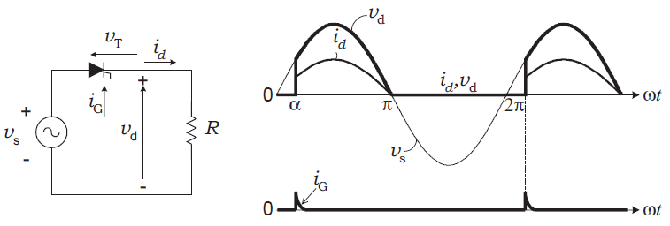
In single-phase half-wave rectifier, only one thyristor is used to control the load voltage. The thyristor will conduct (ON state) when the voltage Vt is positive (Vt > 0) and a firing current pulse Ig is applied to the gate terminal. Delaying the firing pulse by an angle ‘alpha’ does the control of the load voltage. In the figure below the angle ‘alpha’ is measured from the zero crossing point of the supply voltage Vs . The load is resistive and therefore current id has the same waveform as the load voltage. The thyristor goes to the nonconducting condition (OFF state) when the load voltage and, consequently, the current try to reach a negative value.
Components Required:
- Arduino UNO, NANO …
- SCR. I used TYN1225 – datasheet
- 2 x optocoupler. I used PC817 – datasheet
- 2 x IN4007 diode
- 10k ohm resistor
- 10k ohm potentiometer
- 2 x 1k ohm resistor
- Resistive load. I used 100 ohm resistor
- 220 ohm resistor
- 12V AC source (alternating current)
- Breadboard
- Jumper wires
SCR control with Arduino circuit:
Example circuit schematic diagram is shown below.
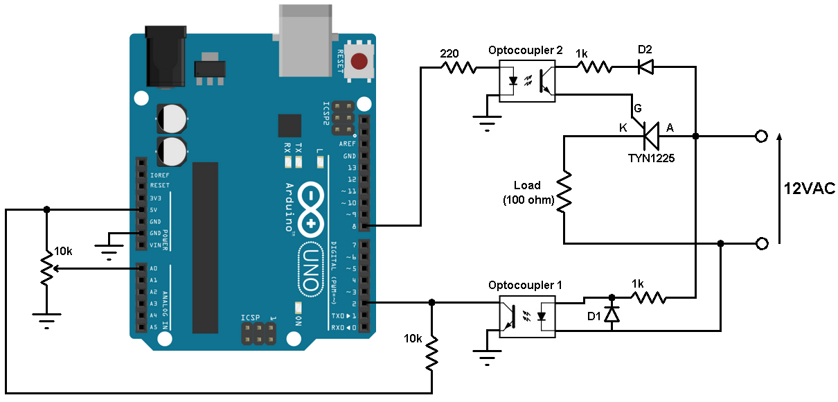
All grounded terminals are connected together.
In the circuit there are two optocouplers, I used optocoupler 1 to detect the zero crossing of the AC voltage signal and optocoupler 2 for firing the SCR. The optocouplers are used to isolate the Arduino (control circuit) from the power circuit.
Diodes D1 and D2 are with the same type (1N4007), D1 is used to protect optocoupler 1 from reverse voltage and D2 to feed the SCR gate with positive current.
Optocoupler 1 collector pin is connected to Arduino pin 2 which is external interrupt pin, so optocoupler 1 interrupts the Arduino when there is a zero crossing event (when the AC signal goes from positive to negative). When the AC voltage is positive, optocoupler 1 is ON and therefore the collector pin is connected to ground. I used the 10k ohm resistor as pull-up resistor for Arduino pin 2 because we’ve an open collector output (optocoupler 1).
The 10k ohm potentiometer is used to control firing angle.
I got the 12V AC (50Hz) using a step down transformer (220V to 12V).
SCR control with Arduino code:
Arduino code is the one below.
1 2 3 4 5 6 7 8 9 10 11 12 13 14 15 16 17 18 19 20 21 22 23 24 25 26 27 28 | // Half wave controlled rectifier with Arduino (SCR controller with Arduino) #define scr_trig 8 #define pot A0 bool ZC = 0; uint16_t alpha; void setup(void) { pinMode(scr_trig, OUTPUT); digitalWrite(scr_trig, LOW); attachInterrupt(0, ZC_detect, FALLING); // Enable external interrupt (INT0) } void ZC_detect() { ZC = 1; } void loop() { if(ZC){ delayMicroseconds(alpha); digitalWrite(scr_trig, HIGH); delay(1); digitalWrite(scr_trig, LOW); ZC = 0; alpha = analogRead(pot) * 10; if(alpha > 10000) alpha = 10000; } } |
The following video shows output waveform and the variation of the firing angle with an oscilloscope:
Reference:
Power Electronics Handbook – MUHAMMAD H. RASHID
Discover more from Simple Circuit
Subscribe to get the latest posts sent to your email.


Your code is not working. There is some problem in interrupt section
Do you know what the correct code is?
Comment adapter le programme pour commander les deux thyristors d’un pont de Graêtz mixte symétrique monophasé?
Hello Sir
What is the name of the simulation you used for oscilloscope?
That is a USB oscilloscope which already comes with its software.
PLz help can we use this with 110V AC instead of 12V AC????
What SCR and gate resistance we should use if we don’t want to use the transformer?
Excuse me.
Hello Sir. i have some problem with my project project for my college. My project is rectifier 3 phase controlled full wave. Do you have for this code of the rectifier 3 phase? Please help me. Thank you sir..
i make this practice with the same code but i don’t have a voltage signal from my arduino at optocupler 2 and i don’t understand the prurpose of the arduino pin 2
hello roberto bujano, pin no 2 is set high at starting for optocupler input, because interrupt is falling edge controller . when ever ac changes from high to low it get falling pulse into arduino i.e int pulse = 2;
at void main
witer , pinMode(pulse,OUTPUT)
digitalWrite(pulse,HIGH) all the time
Like ..
What are the use cases ? Where is this used ? What purpose does this serve ?
You can say that it’s just an introduction to controlled bridge rectifier which is used in many cases like battery charger, motor control (for example in industry) …