Last time I made a simple half-wave controlled rectifier using Arduino and thyristor (SCR), and in this topic shows how did I built a full-wave bridge rectifier using Arduino (half-controlled bridge rectifier).
Previous project link is the one below:
SCR control with Arduino – Half-wave controlled rectifier
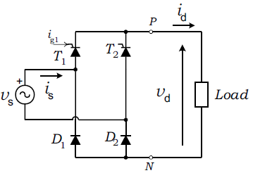
The figure below shows the half-controlled bridge rectifier, which uses two thyristors and two diodes:
Hardware Required:
- Arduino board – ATmega328P datasheet
- 2 x Thyristor (SCR). I used TYN1225 —> datasheet
- 2 x optocoupler. I used PC817 —> datasheet
- LM393 (or LM339) comparator —> datasheet
- 6 x IN4007 diode
- 10k ohm resistor
- 10k ohm potentiometer
- 4 x 1k ohm resistor
- Resistive load. I used 270 ohm resistor
- 2 x 220 ohm resistor
- 220V to 12V step down transformer
- Breadboard
- Jumper wires
Controlled bridge rectifier with Arduino circuit:
Project circuit schematic diagram is shown below.
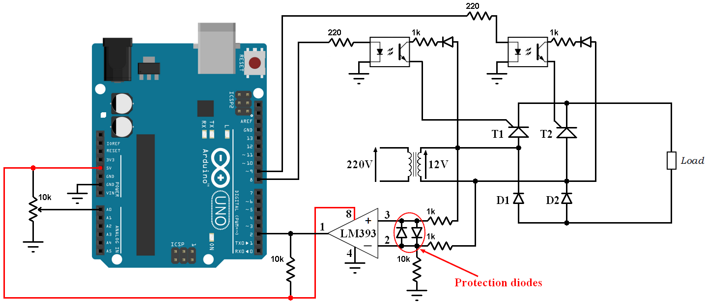
All grounded terminals are connected together.
The rectifier bridge consists of two thyristors T1, T2 and two diodes D1 , D2 (half controlled bridge rectifier). The transformer is used to step down the 220V into 12V.
In the circuit there are two optocouplers, each one is used to fire one thyristor (give current to the gate of the thyristor), thyristor T1 is fired with Arduino pin 8 and thyristor T2 is fired with arduino pin 9.
In this example I used the LM393 (dual comparator IC) for the zero crossing detection, an optocoupler can be used for the same purpose but I think the comparator is better. The two diodes which are connected between the non-inverting input (+) and the inverting input (-) of the comparator are used to limit the voltage across those pins (the LM393 can work directly with 12V, so they are optional). The output of the LM393 (or LM339) is an open collector, so I added the 10k ohm resistor there (between +5V and arduino pin 2). Also the comparator chip is supplied with +5V which comes from the Arduino board.
In this example I used a resistive load with resistance of 270 ohm
The 10k ohm potentiometer is used to control firing angle.
Arduino code:
Full Arduino code is below.
1 2 3 4 5 6 7 8 9 10 11 12 13 14 15 16 17 18 19 20 21 22 23 24 25 26 27 28 29 30 31 32 33 34 35 36 37 38 39 40 | // Controlled bridge rectifier with Arduino #define scr1_gate 8 #define scr2_gate 9 #define pot A0 byte ZC = 0; uint16_t alpha; void setup(void) { pinMode(scr1_gate, OUTPUT); digitalWrite(scr1_gate, LOW); pinMode(scr2_gate, OUTPUT); digitalWrite(scr2_gate, LOW); attachInterrupt(0, ZC_detect, CHANGE); // Enable external interrupt (INT0) } void ZC_detect() { if(digitalRead(2)) ZC = 1; else ZC = 2; } void loop() { if(ZC == 1){ delayMicroseconds(alpha); digitalWrite(scr1_gate, HIGH); delay(2); digitalWrite(scr1_gate, LOW); alpha = analogRead(pot) * 7; ZC = 0; } if(ZC == 2){ delayMicroseconds(alpha); digitalWrite(scr2_gate, HIGH); delay(2); digitalWrite(scr2_gate, LOW); alpha = analogRead(pot) * 7; ZC = 0; } } |
The following video shows output waveform and the variation of the firing angle:
Reference:
Power Electronics Handbook – MUHAMMAD H. RASHID
Discover more from Simple Circuit
Subscribe to get the latest posts sent to your email.


did anyone get this right? help me please
Hello Can i get this proteus simulation.
Can anyone help me about this project?
Any changes needed to use this with 120 VAC, other than the step down transformer?
I’m looking to control it remotely, wirelessly, can I use a PWM output pin to control it instead of a manual 10K pot?
Thanks, DougRH
I’m looking for speed control of 120 VAC motors. Would this work with brushless, induction motors as well as brushed motors?
&/or an Analog output pin as well as a PWM digital IO pin on an Arduino?
I need A similar circuit to run on 120 volts, with out the step down transformer.
Can some anybody help me, has anyone done that before, this circuit is good, but is not what I need and I won’t know how to modify it my self.
This project may help you:
http://simple-circuit.com/arduino-220v-full-wave-controlled-bridge-rectifier/
It’s for 220/230V but it may work with 110/120V.
i cant run my simulation if i use TYN1225 thyristor..help me please
looks good yall!
how do I use 220v straight without stepping down to 12v on the circuit of controlling the the bridge rectifier.
how do I use it on 220V straight without stepping down to 12V.
Can you please tell me how you get firing andgle by multiplying with 7
yea i need to know that too please
I am not able to control the alpha with potentiometer. The code is same as yours, still my alpha is not changed. Please help me out through this.
Did your project runs successfully?
What do I need to change if i want to operate the same circuit without step down, i.e. at 220v ?