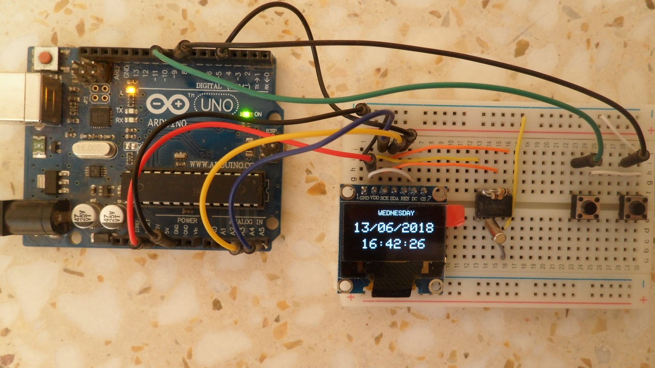
This post shows how to build a real time clock using Arduino, DS1307 RTC and SSD1306 OLED. The DS1307 RTC is used as a real time clock chip which keeps the time running even if the main power supply is off (with the help of a battery), time and date are displayed on the SSD1306 128×64 OLED.
In this Arduino project the DS1307 RTC as well as the SSD1306 OLED share the same I2C bus which minimizes the pin used. The I2C bus has two lines: SDA (serial data) and SCL (serial clock), an addition rest pin is required for the SSD1306 OLED. So with two push buttons we need a total of 5 pins. The two push buttons are used to set our real time clock (time and date).
Related Projects:
The two posts below contain some useful information which may help building this project.
Interfacing Arduino with SSD1306 OLED display
Arduino real time clock with DS1307
Hardware Required:
- Arduino board
- DS1307 RTC — datasheet
- SSD1306 OLED (I2C mode)
- 32.768KHz crystal oscillator
- 2 x 10K ohm resistor
- 2 x push button
- 3V coin cell battery
- Breadboard
- Jumper wires
The SSD1306 OLED used in this project is configured to work in I2C mode, some SSD1306 OLED boards may require a small hardware modifications (to select between SPI mode or I2C mode) such as soldering, placing jumpers …
In this project I used Adafruit SSD1306 OLED driver and Adafruit GFX library. Both libraries can be downloaded through Arduino IDE Library Manager of manually from the links below (after downloading, unzip the folders and place them in Arduino libraries folder, for example C:\Program Files\Arduino\libraries)
Adafruit SSD1306 OLED library — direct link
Adafruit GFX library — direct link
Arduino real time clock using DS1307 and SSD1306 OLED circuit:
Project circuit diagram is shown below.
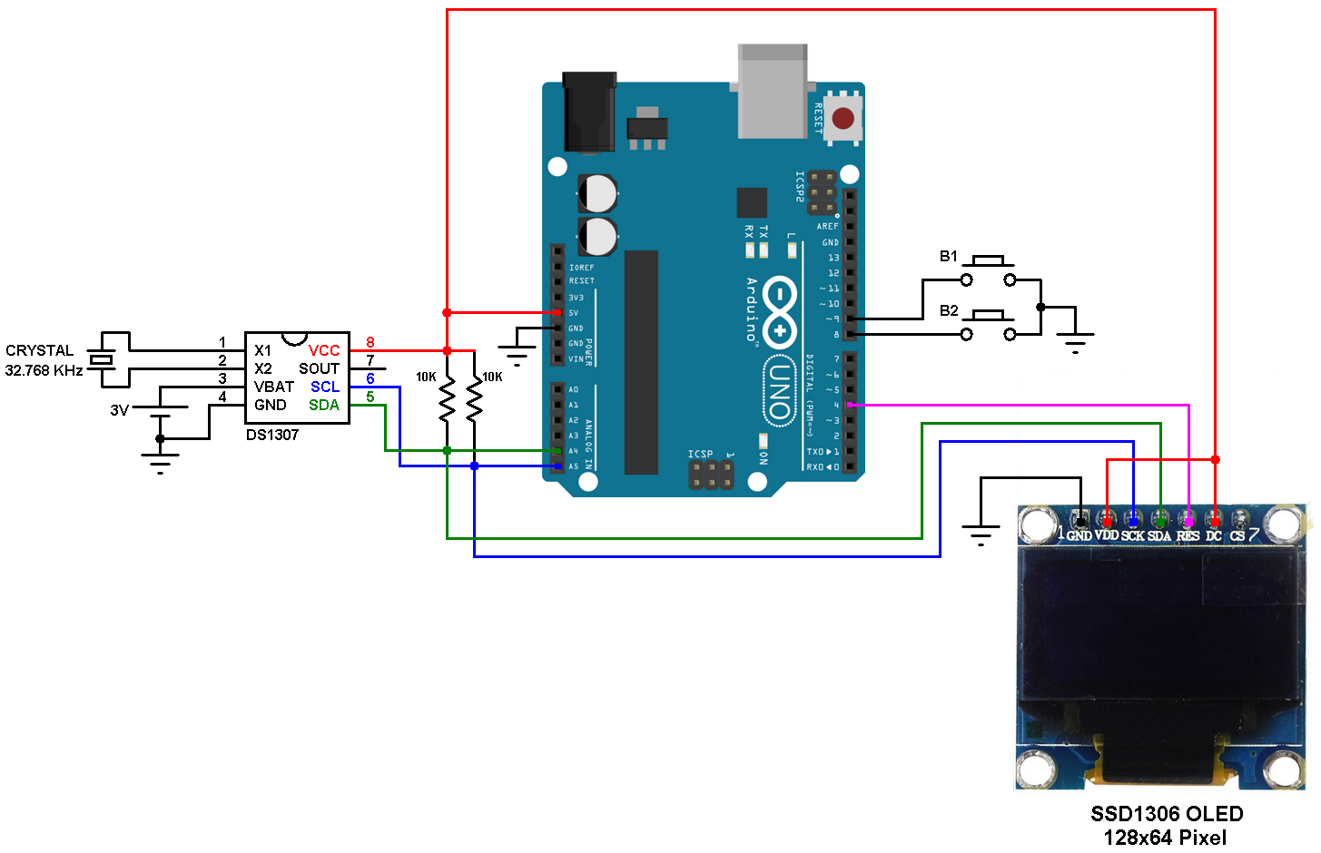
(All grounded terminals are connected together)
The two push buttons B1 and B2 are for setting time and date.
Arduino Code:
SSD1306 OLED and DS1307 RTC share the same I2C bus and the Arduino communicates only with 1 device at a time depending on the address (sent by the Arduino), the SSD1306 address is 0x3D and the DS1307 address is 0x68.
The Arduino code below uses Adafruit SSD1306 OLED driver and Adafruit GFX library. It doesn’t use any library for the DS1307 RTC.
1 2 3 4 5 6 7 8 9 10 11 12 13 14 15 16 17 18 19 20 21 22 23 24 25 26 27 28 29 30 31 32 33 34 35 36 37 38 39 40 41 42 43 44 45 46 47 48 49 50 51 52 53 54 55 56 57 58 59 60 61 62 63 64 65 66 67 68 69 70 71 72 73 74 75 76 77 78 79 80 81 82 83 84 85 86 87 88 89 90 91 92 93 94 95 96 97 98 99 100 101 102 103 104 105 106 107 108 109 110 111 112 113 114 115 116 117 118 119 120 121 122 123 124 125 126 127 128 129 130 131 132 133 134 135 136 137 138 139 140 141 142 143 144 145 146 147 148 149 150 151 152 153 154 155 156 157 158 159 160 161 162 163 164 165 166 167 168 169 170 171 172 173 174 175 176 177 178 179 180 181 182 183 184 | // Arduino real time clock with DS1307 and SSD1306 OLED #include <Wire.h> // Include Wire library (required for I2C devices) #include <Adafruit_GFX.h> // Include Adafruit graphics library #include <Adafruit_SSD1306.h> // Include Adafruit SSD1306 OLED driver #define OLED_RESET 4 Adafruit_SSD1306 display(OLED_RESET); #define button1 9 // Button B1 is connected to Arduino pin 9 #define button2 8 // Button B2 is connected to Arduino pin 8 void setup(void) { pinMode(button1, INPUT_PULLUP); pinMode(button2, INPUT_PULLUP); delay(1000); // by default, we'll generate the high voltage from the 3.3v line internally! (neat!) display.begin(SSD1306_SWITCHCAPVCC, 0x3D); // initialize with the I2C addr 0x3D (for the 128x64) // init done // Clear the display buffer. display.clearDisplay(); display.display(); display.setTextColor(WHITE, BLACK); } char Time[] = " : : "; char Calendar[] = " / /20 "; byte i, second, minute, hour, day, date, month, year; void display_day(){ switch(day){ case 1: draw_text(40, 0, " SUNDAY ", 1); break; case 2: draw_text(40, 0, " MONDAY ", 1); break; case 3: draw_text(40, 0, " TUESDAY ", 1); break; case 4: draw_text(40, 0, "WEDNESDAY", 1); break; case 5: draw_text(40, 0, "THURSDAY ", 1); break; case 6: draw_text(40, 0, " FRIDAY ", 1); break; default: draw_text(40, 0, "SATURDAY ", 1); } } void DS1307_display(){ // Convert BCD to decimal second = (second >> 4) * 10 + (second & 0x0F); minute = (minute >> 4) * 10 + (minute & 0x0F); hour = (hour >> 4) * 10 + (hour & 0x0F); date = (date >> 4) * 10 + (date & 0x0F); month = (month >> 4) * 10 + (month & 0x0F); year = (year >> 4) * 10 + (year & 0x0F); // End conversion Time[7] = second % 10 + 48; Time[6] = second / 10 + 48; Time[4] = minute % 10 + 48; Time[3] = minute / 10 + 48; Time[1] = hour % 10 + 48; Time[0] = hour / 10 + 48; Calendar[9] = year % 10 + 48; Calendar[8] = year / 10 + 48; Calendar[4] = month % 10 + 48; Calendar[3] = month / 10 + 48; Calendar[1] = date % 10 + 48; Calendar[0] = date / 10 + 48; draw_text(4, 18, Calendar, 2); draw_text(16, 42, Time, 2); } void blink_parameter(){ byte j = 0; while(j < 10 && digitalRead(button1) && digitalRead(button2)){ j++; delay(25); } } byte edit(byte x_pos, byte y_pos, byte parameter){ char text[3]; sprintf(text,"%02u", parameter); while(!digitalRead(button1)); // Wait until button B1 released while(true){ while(!digitalRead(button2)){ // If button B2 is pressed parameter++; if(i == 0 && parameter > 31) // If date > 31 ==> date = 1 parameter = 1; if(i == 1 && parameter > 12) // If month > 12 ==> month = 1 parameter = 1; if(i == 2 && parameter > 99) // If year > 99 ==> year = 0 parameter = 0; if(i == 3 && parameter > 23) // If hours > 23 ==> hours = 0 parameter = 0; if(i == 4 && parameter > 59) // If minutes > 59 ==> minutes = 0 parameter = 0; sprintf(text,"%02u", parameter); draw_text(x_pos, y_pos, text, 2); delay(200); // Wait 200ms } draw_text(x_pos, y_pos, " ", 2); blink_parameter(); draw_text(x_pos, y_pos, text, 2); blink_parameter(); if(!digitalRead(button1)){ // If button B1 is pressed i++; // Increament 'i' for the next parameter return parameter; // Return parameter value and exit } } } void draw_text(byte x_pos, byte y_pos, char *text, byte text_size) { display.setCursor(x_pos, y_pos); display.setTextSize(text_size); display.print(text); display.display(); } void loop() { if(!digitalRead(button1)){ // If button B1 is pressed i = 0; while(!digitalRead(button1)); // Wait for button B1 release while(true){ while(!digitalRead(button2)){ // While button B2 pressed day++; // Increment day if(day > 7) day = 1; display_day(); // Call display_day function delay(200); // Wait 200 ms } draw_text(40, 0, " ", 1); blink_parameter(); // Call blink_parameter function display_day(); // Call display_day function blink_parameter(); // Call blink_parameter function if(!digitalRead(button1)) // If button B1 is pressed break; } date = edit(4, 18, date); // Edit date month = edit(40, 18, month); // Edit month year = edit(100, 18, year); // Edit year hour = edit(16, 42, hour); // Edit hours minute = edit(52, 42, minute); // Edit minutes // Convert decimal to BCD minute = ((minute / 10) << 4) + (minute % 10); hour = ((hour / 10) << 4) + (hour % 10); date = ((date / 10) << 4) + (date % 10); month = ((month / 10) << 4) + (month % 10); year = ((year / 10) << 4) + (year % 10); // End conversion // Write data to DS1307 RTC Wire.beginTransmission(0x68); // Start I2C protocol with DS1307 address Wire.write(0); // Send register address Wire.write(0); // Reset sesonds and start oscillator Wire.write(minute); // Write minute Wire.write(hour); // Write hour Wire.write(day); // Write day Wire.write(date); // Write date Wire.write(month); // Write month Wire.write(year); // Write year Wire.endTransmission(); // Stop transmission and release the I2C bus delay(200); // Wait 200ms } Wire.beginTransmission(0x68); // Start I2C protocol with DS1307 address Wire.write(0); // Send register address Wire.endTransmission(false); // I2C restart Wire.requestFrom(0x68, 7); // Request 7 bytes from DS1307 and release I2C bus at end of reading second = Wire.read(); // Read seconds from register 0 minute = Wire.read(); // Read minuts from register 1 hour = Wire.read(); // Read hour from register 2 day = Wire.read(); // Read day from register 3 date = Wire.read(); // Read date from register 4 month = Wire.read(); // Read month from register 5 year = Wire.read(); // Read year from register 6 display_day(); DS1307_display(); // Diaplay time & calendar delay(50); // Wait 50ms } // End of code. |
Project simulation:
The video below shows the simulation of the project with Proteus ISIS. Note that the simulation circuit is not the same as the actual hardware circuit, project hardware circuit is shown above (don’t try to build your hardware circuit as shown in the simulation video, otherwise your circuit may not work or you’ll damage your components!).
Proteus simulation file download (for version 8.6 or higher):
Arduino + SSD1306 OLED + DS1307
Discover more from Simple Circuit
Subscribe to get the latest posts sent to your email.


Thanks for sharing ?
how can we increase/decrease minutes,hour, date with 2 buttons.
i dont want to keep increasing the minute is i passed the wanted minute
what kind of wire library did you use? can you please reply my comment
The Arduino built-in wire library.
This project displays only day of week and date.
It displays also the time, but not on a valid coordinates.