This topic shows how to interface Arduino UNO board with SSD1306 OLED display (128×64 pixel). The SSD1306 is a monochrome display which means it has only one color (white, blue, yellow …). Also we’ll show how to simulate the SSD1306 display using Proteus ISIS.
The SSD1306 display contains a driver chip with the same name (SSD1306), it can communicate with the master device (microcontroller, microprocessor …) over I2C protocol, SPI protocol or 8-bit parallel protocol. In this topic I’m going to show how to use I2C and SPI protocols with this display.
The I2C protocol needs only 2 lines: SDA (serial data) and SCK (serial clock), an additional line is required which is a reset line (RST). The SPI protocol is faster than the I2C protocol but it uses more pins: SCK, SDA, CS (chip select: active low), D/C (data/command) and a rest pin (RST).
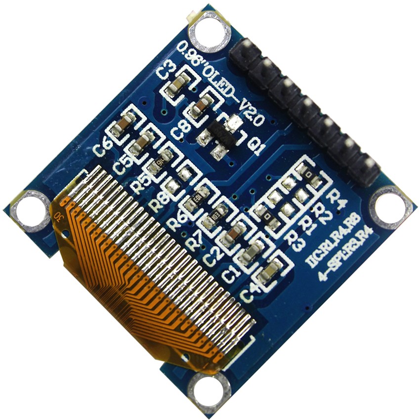
The SSD1306 OLED which I used is shown below (back view), the default mode is SPI which can be changed to I2C by removing the resistors R3 and placing the resistors R1 & R8 (as written on the board). Note that resistance of R1 = R3 = R8 = 0 ohm.
Hardware Required:
- Arduino board
- SSD1306 OLED display
- Breadboard
- Jumper wires
SSD1306 OLED driver for Arduino:
Adafruit Industries provides a very nice library for the SSD1306 OLED, it can be easily installed using Arduino library manager (Sketch —> Include Library —> Library Manager), or manually by downloading it from the link below and adding it to Arduino libraries folder (C:\Program Files\Arduino\libraries):
Adafruit SSD1306 OLED library
Note that the Adafruit SSD1306 OLED driver supports 3 types: 128×64, 128×32 and 96×16 pixel, we can select between them in the driver file Adafruit_SSD1306.h. Opening the file with a text editor such as the Arduino IDE gives (scroll down as shown):
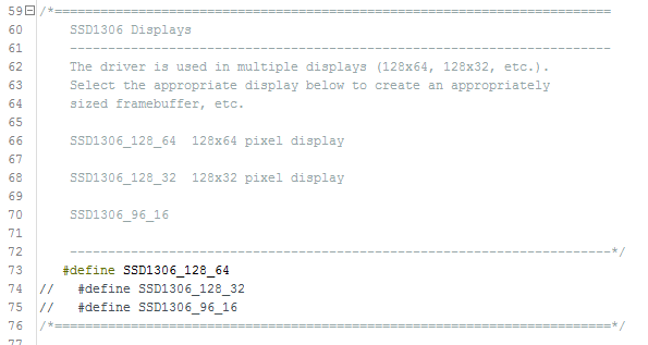
I commented the default display type #define SSD1306_128_32 and uncommented #define SSD1306_128_64 because I’m using 128×64 pixel display (0.96″).
We need an other library named Adafruit GFX (graphics library) which can be installed through Arduino library manager or manually by downloading it from the link below:
Adafruit GFX library
Using SSD1306 with SPI mode (4-wire SPI):
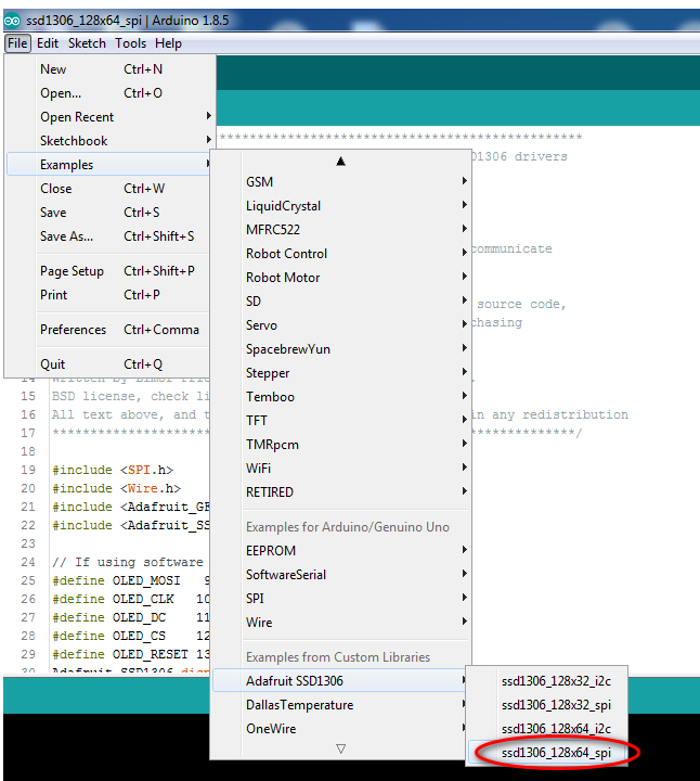
The SSD1306 library comes with 4 examples, one of them is using the SSD1306 OLED with SPI mode. We can open the example by going to Arduino IDE:
File —> Examples —> Adafruit SSD1306 —> ssd1306_128x64_spi
as shown in the image below:
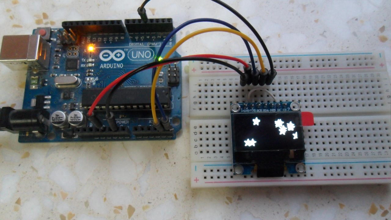
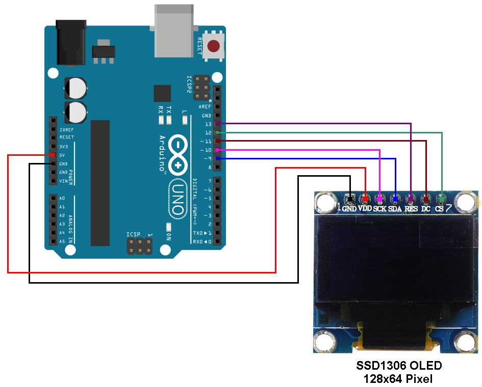
Example circuit connections are shown below where:
GND goes to GND (ground)
VDD to 5V
SDA (serial data) to digital pin 9
SCK (serial clock) to digital pin 10
DC (data/command) to digital pin 11
CS (chip select) to digital pin 12
RES (reset) to digital pin 13
Proteus simulation:
This example works with Proteus simulation software since it (Proteus) contains the SSD1306 OLED library. The video below shows the simulation result:
Proteus simulation file download (for version 8.6 and higher):
Arduino + SSD1306 OLED SPI
Using SSD1306 OLED with I2C mode:
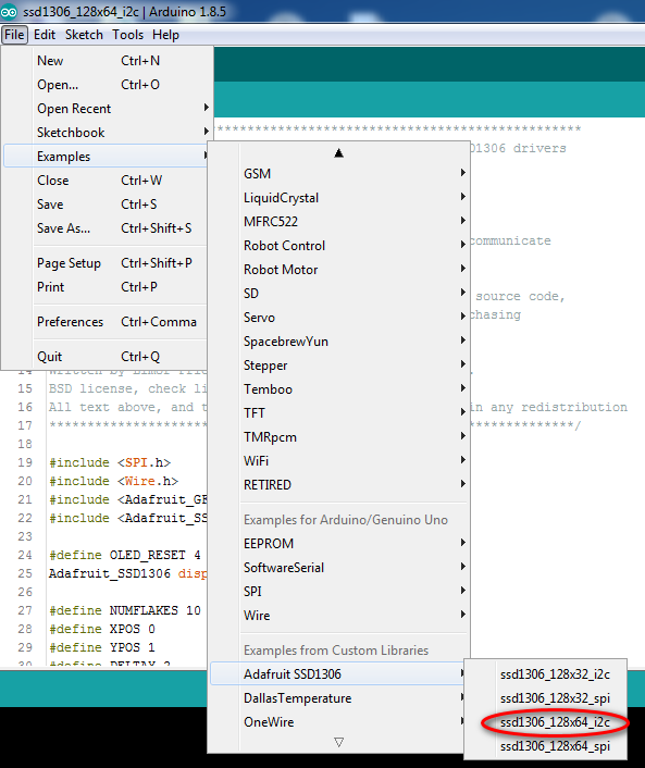
The second Adafruit example is SSD1306 OLED with I2C (IIC or: Inter-Integrated Circuit). We can open it by going to Arduino IDE:
File —> Examples —> Adafruit SSD1306 —> ssd1306_128x64_i2c
as shown in the image below:
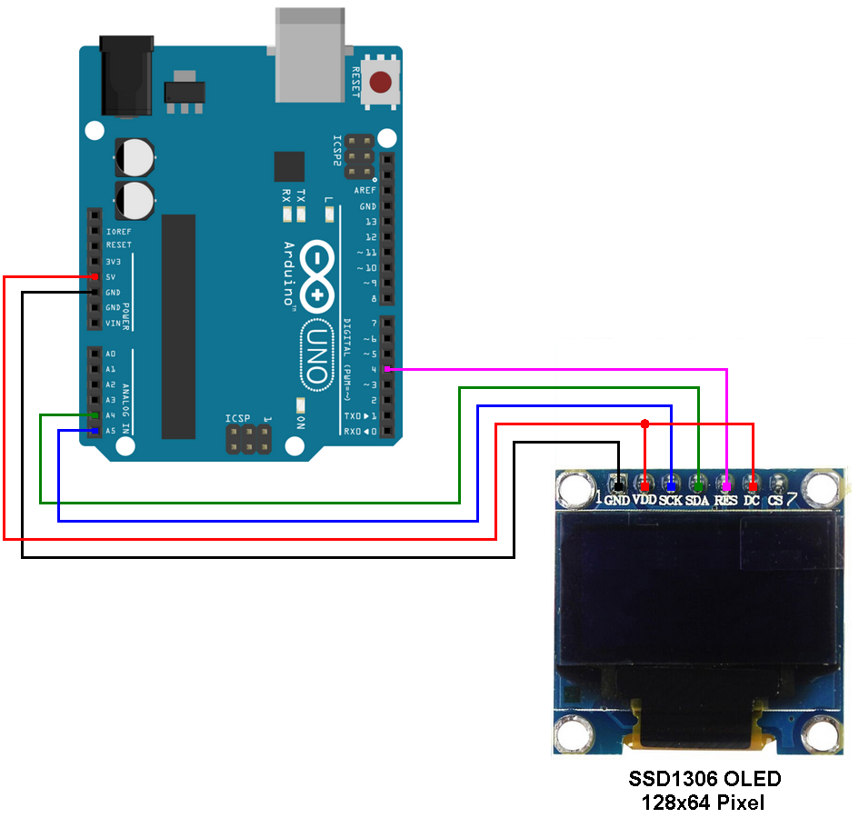
Example circuit connections are shown below where:
GND goes to GND (ground)
VDD to 5V
SDA (serial data) to pin A4 (Arduino UNO I2C SDA pin)
SCK (serial clock) to pin A5 (Arduino UNO I2C SCL pin)
RES (reset) to digital pin 4
The following video shows the simulation of the example using Proteus ISIS:
and the second video shows a simple hardware circuit:
Proteus simulation file download (for version 8.6 and higher):
Arduino + SSD1306 OLED I2C
Arduino projects with SSD1306 OLED display:
Arduino with SSD1306 OLED and DHT11/DHT22 sensor
Arduino real time clock using DS1307 and SSD1306 OLED
Real time clock using NodeMCU, DS3231 and SSD1306 OLED
Arduino with DS18B20 sensor and SSD1306 OLED display
Arduino with SSD1306 OLED display and LM35 temperature sensor
Arduino with BMP280 pressure & temperature sensor and SSD1306 OLED
Arduino weather station with SSD1306 OLED and BME280 sensor
Discover more from Simple Circuit
Subscribe to get the latest posts sent to your email.


Very good article
thank you for your explanation but would you mined sending OLED display proteus library please?
PROVIDE THE PROTEUS LIB FOR SSD1306 OLED display:
Milyen izgalmas, és teljes lenne a példa,ha a 4 pin kivezetéses I2C-vel kommunikáló 0.96 OLED 128×64 display is bekerült volna a példák közzé DS3231 óra modullal és DHT22 hőmérő szenzorral és 2 nyomógombbal