This tutorial shows how to interface Arduino UNO board with SSD1306 OLED display and LM35 analog temperature sensor.
In this project the SSD1306 OLED display (128×64 pixel) is used to display environment temperature in degree Celsius, Kelvin and degree Fahrenheit.
To see how to interface Arduino with SSD1306 OLED display, visit the following post:
Interfacing Arduino with SSD1306 OLED display
In this project the SSD1306 OLED is configured to work in I2C mode, make sure that your display is configured to work in I2C mode, some displays need jumper placing or some soldering.
The LM35 temperature sensor is a three pin device (VCC, OUT and GND) with an output voltage linearly related to Centigrade temperature. Since the LM35 output varies with dependent to the temperature, we need an ADC (Analog-to-Digital Converter) module to measure this voltage. Arduino UNO microcontroller (Microchip ATmega328P) has one ADC module with 10-bit resolution.
The LM35 output has linear +10mV/°C scale factor means the following:
If the output voltage = 10mV —> temperature = 1°C
If the output voltage = 100mV —> temperature = 10°C
If the output voltage = 200mV —> temperature = 20°C
If the output voltage = 370mV —> temperature = 37°C
and so on.
LM35 Futures (from datasheet):
- Calibrated Directly in ° Celsius (Centigrade)
- Linear + 10 mV/°C Scale Factor
- 0.5°C Ensured Accuracy (at +25°C)
- Rated for Full −55°C to +150°C Range
- Suitable for Remote Applications
- Low Cost Due to Wafer-Level Trimming
- Operates from 4 to 30 V
- Less than 60-μA Current Drain
- Low Self-Heating, 0.08°C in Still Air
- Nonlinearity Only ±¼°C Typical
- Low Impedance Output, 0.1 Ω for 1 mA Load
The ADC module converts analog data into digital data. The ATmega328P MCU has a 10-bit ADC module and a built-in reference voltage of 1.1V. Using the reference voltage should give better results.
Normally negative and positive references of the ADC module are VSS and VDD respectively, but VDD is not exactly equal to 5.00V, hence we should use the reference voltage (1.1V) as a positive reference of the ADC module.
Hardware Required:
- Arduino board
- SSD1306 OLED display
- LM35 temperature sensor —-> datasheet
- Breadboard
- Jumper wires
Arduino with SSD1306 OLED display and LM35 temperature sensor circuit:
The image below shows project circuit schematic diagram.
The LM35 sensor has 3 pins (from left to right):
Pin 1 is power supply pin, connected to Arduino 5V pin
Pin 2: output pin, connected to Arduino analog pin 0 (A0)
Pin 3: GND (ground), connected to Arduino GND pin.
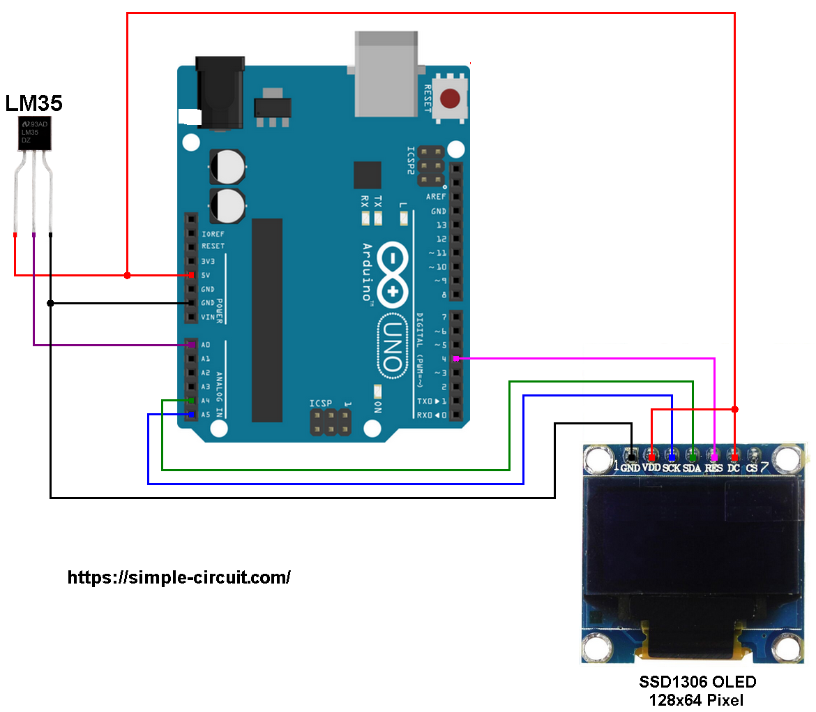
The SSD1306 OLED display is connected to the Arduino UNO board as follows:
SSD1306 OLED GND goes to Arduino GND (ground),
SSD1306 OLED VDD to Arduino 5V,
SSD1306 OLED SDA pin (serial data) to pin A4 (Arduino UNO hardware I2C SDA pin),
SSD1306 OLED SCK pin (serial clock) to pin A5 (Arduino UNO hardware I2C SCL pin),
SSD1306 OLED RES pin (reset) to Arduino pin 4.
The SSD1306 OLED display DC pin is connected to VDD which means I2C slave address of the device is 0x3D. If the DC pin is connected to ground (GND) then the I2C slave address will be 0x3C.
Arduino with SSD1306 OLED display and LM35 temperature sensor code:
The following Arduino code requires 2 libraries from Adafruit Industries:
The first library is a driver for the SSD1306 OLED display which can be installed from Arduino IDE library manager (Sketch —> Include Library —> Manage Libraries …, in the search box write “ssd1306” and install the one from Adafruit).
The second library is Adafruit graphics library which can be installed also from Arduino IDE library manager.
The previous 2 libraries can also be installed manually, download links are below:
Adafruit SSD1306 OLED driver —-> direct link
Adafruit graphics library —-> direct link
After the download, go to Arduino IDE —> Sketch —> Include Library —> Add .ZIP Library … and browse for the .zip file (previously downloaded).
The same thing for the other library file.
In the code there are total of 3 libraries, they’re included in the code as follows:
1 2 3 | #include <Wire.h> // include Arduino wire library (required for I2C devices) #include <Adafruit_GFX.h> // include Adafruit graphics library #include <Adafruit_SSD1306.h> // include Adafruit SSD1306 OLED display driver |
The SSD1306 OLED display reset pin and LM35 analog temperature sensor pin connections are defined in the code as shown below:
1 2 3 4 5 | #define OLED_RESET 4 // define display reset pin Adafruit_SSD1306 display(OLED_RESET); // define LM35 data pin connection #define LM35_PIN A0 |
Reading voltage quantity using the ADC gives a number between 0 and 1023 (10-bit resolution), 0V is represented by 0 and 1.1V is represented by 1023 (ADC positive reference is 1.1V) . Converting back the ADC digital value is easy, we can use the following equation:
Voltage (in Volts) = ADC reading * 1.1 / 1023
Multiplying the previous result by 100 (LM35 scale factor is 10mV/°C = 0.01V/°C) gives the actual temperature:
Temperature( °C) = ADC reading * 0.1075 , or
Temperature( °C) = ADC reading / 9.3
where: 0.1075 = 100 * 1.1 / 1023 and 9.3 = 1 / 0.1075
To use the internal 1.1V reference I used the command: analogReference(INTERNAL);
In this example I used one number after the decimal point, multiplying the temperature by 10 gives the temperature in tenths degree Celsius (output value of “274” equals 27.4 °Celsius), so the final result is:
1 | tCelsius = 10 * analogRead(LM35_pin) / 9.3; |
The temperature in tenths degree Fahrenheit = (tenth °Celsius) x 9/5 +320 (because: °F = °Cx9/5 + 32) and the temperature in tenths Kelvin = (tenth °Celsius) + 2732 (because: K = °C + 273.16).
To get the actual value of each quantity we’ve to divide it by 10. The line below shows an example for temperature in Kelvin:
1 | sprintf(_buffer, "%03u.%1u K", tKelvin / 10, tKelvin % 10); |
We get the first 3 digits by dividing the tenths value by 10, and the tenths number (number after the decimal point) of the actual temperature value is equal to the reminder of that division (tenths value % 10).
The resolution of this thermometer is 0.1°C.
Full Arduino code:
1 2 3 4 5 6 7 8 9 10 11 12 13 14 15 16 17 18 19 20 21 22 23 24 25 26 27 28 29 30 31 32 33 34 35 36 37 38 39 40 41 42 43 44 45 46 47 48 49 50 51 52 53 54 55 56 57 58 59 60 61 62 63 64 65 66 67 68 69 70 71 72 73 74 75 76 77 78 79 80 | /* * Arduino with LM35 analog temperature sensor and SSD1306 OLED display. * This is a free software with NO WARRANTY. * http://simple-circuit.com/ */ #include <Wire.h> // include Arduino wire library (required for I2C devices) #include <Adafruit_GFX.h> // include Adafruit graphics library #include <Adafruit_SSD1306.h> // include Adafruit SSD1306 OLED display driver #define OLED_RESET 4 // define display reset pin Adafruit_SSD1306 display(OLED_RESET); // define LM35 data pin connection #define LM35_pin A0 void setup(void) { delay(1000); // wait a second analogReference(INTERNAL); // set positive reference voltage to 1.1V // initialize the SSD1306 OLED display with I2C address = 0x3D display.begin(SSD1306_SWITCHCAPVCC, 0x3D); // clear the display buffer. display.clearDisplay(); display.setTextSize(1); // text size = 1 display.setTextColor(WHITE, BLACK); // set text color to white and black background display.setCursor(15, 0); // move cursor to position (15, 0) pixel display.print("LM35 TEMPERATURE:"); display.display(); // update the display display.setTextSize(2); // text size = 2 } int tKelvin, tCelsius, tFahrenheit; char _buffer[8]; void loop() { // read analog voltage ( = tenths degree Celsius) // 9.3 = 1023/(1.1*100) tCelsius = 10 * analogRead(LM35_pin) / 9.3; tKelvin = tCelsius + 2732; // convert tenths °C to tenths Kelvin tFahrenheit = tCelsius * 9/5 + 320 ; // convert tenths °C to tenths °Fahrenheit // print temperature in degree Celsius if (tCelsius >= 1000) // if temperature >= 100.0 °C sprintf(_buffer, "%03u.%1u C", tCelsius / 10, tCelsius % 10); else sprintf(_buffer, " %02u.%1u C", tCelsius / 10, tCelsius % 10); display.setCursor(23, 10); display.print(_buffer); // print temperature in degree Fahrenheit if (tFahrenheit >= 1000) // if temperature >= 100.0 °F sprintf(_buffer, "%03u.%1u F", tFahrenheit / 10, tFahrenheit % 10); else sprintf(_buffer, " %02u.%1u F", tFahrenheit / 10, tFahrenheit % 10); display.setCursor(23, 30); display.print(_buffer); // print temperature in Kelvin sprintf(_buffer, "%03u.%1u K", tKelvin/10, tKelvin%10); display.setCursor(23, 50); display.print(_buffer); // print degree symbols ( ° ) display.drawCircle(88, 12, 2, WHITE); display.drawCircle(88, 32, 2, WHITE); // update the display display.display(); delay(1000); // wait a second } // end of code. |
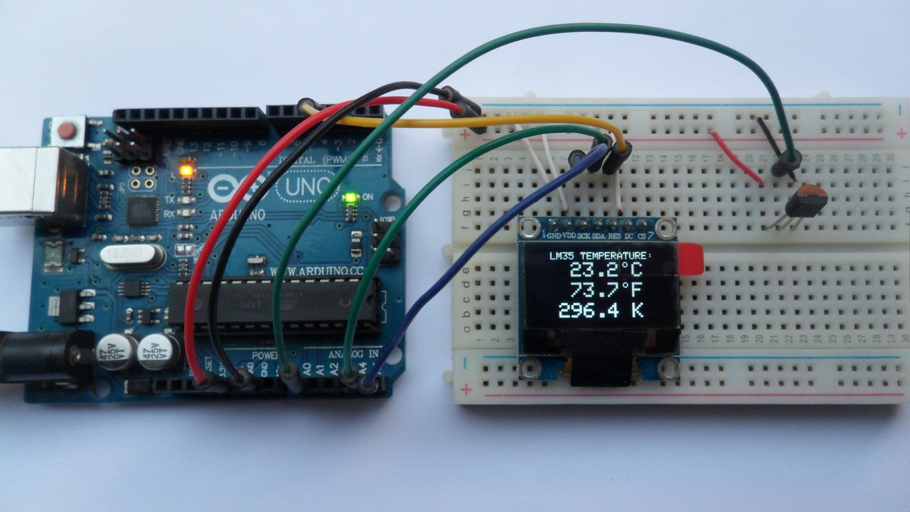
The following picture shows a protoboard circuit of the project:
Discover more from Simple Circuit
Subscribe to get the latest posts sent to your email.


