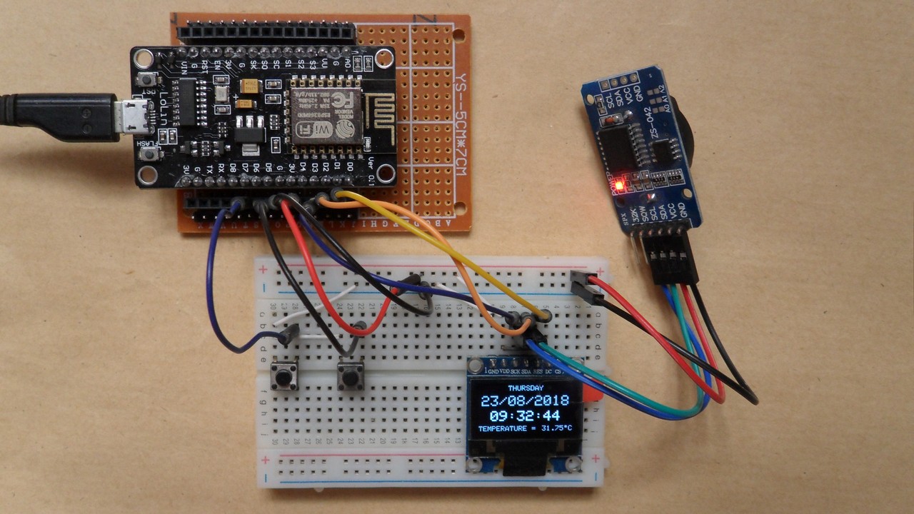
This NodeMCU project shows how to build a real time clock with this development board, DS3231 RTC chip and SSD1306 OLED display (128×64 Pixel).
The DS3231 RTC has a built-in temperature sensor, we could use this sensor to detect and read the temperature of the chip, the SSD1306 screen will also display this temperature.
The DS3231 uses I2C interface to communicate with the master device which is in this case the ESP8266 NodeMCU board. That means the DS3231 and the SSD1306 OLED screen share the same I2C bus. Even they share the same bus but at any time the microcontroller ‘speaks’ with 1 device only depending on the address sent. The DS3231 RTC address is 0x68 and the SSD1306 OLED address is 0x3D.
In the circuit there are two push buttons for setting time and date of the real time clock.
The SSD1306 OLED used in this project is configured to work in I2C mode, some SSD1306 OLED boards may require a small hardware modifications (to select between SPI mode or I2C mode) such as soldering, placing jumpers ….
Related Projects:
ESP8266 NodeMCU interfacing with SSD1306 OLED
ESP8266 ESP-01 Real time clock with DS3231/DS1307
Arduino real time clock with temperature monitor using DS3231 and SSD1306
Hardware Required:
- ESP8266 NodeMCU development board
- SSD1306 OLED display with 128×64 Pixel resolution
- DS3231 board — DS3231 RTC datasheet
- 2 x push button
- 3V coin cell battery
- micro USB cable (for programming and powering the circuit)
- Breadboard
- Jumper wires
NodeMCU + DS3231 RTC + SSD1306 OLED circuit:
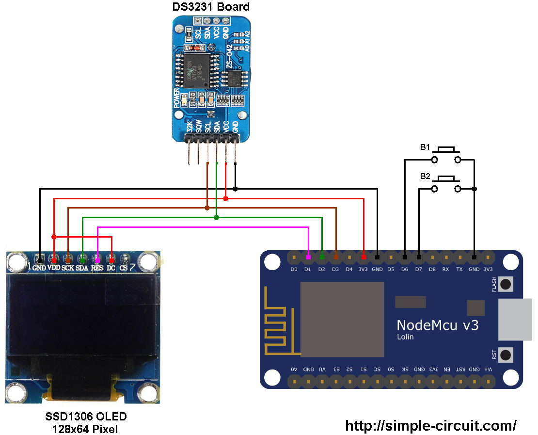
The following image shows project circuit schematic diagram.
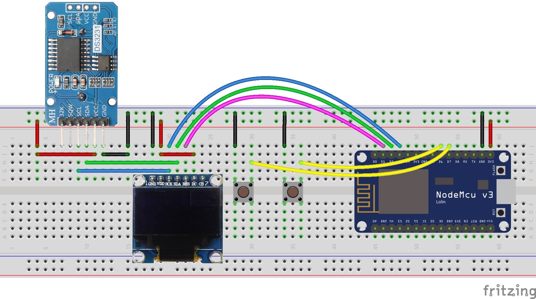
and the second one shows fritzing circuit:
The SDA and SCL lines of the I2C bus come from GPIO4 (D2) and GPIO0 (D3) of the NodeMCU board (respectively), they are connected to SDA and SCL (SCK) pins of the SSD1306 display module. Also, they are connected to SDA and SCL pins of the DS3231 module.
Reset pin (RES) of the display module is connected to GPIO5 (D1) of the NodeMCU development board.
The two push buttons B1 and B2 are for setting time and date. Button B1 is connected to pin GPIO12 (D6) and B2 is connected to pin GPIO13 (D7) of the NodeMCU. Internal pull-ups for the two input pins are enabled in the code.
The SSD1306 display module and the DS3231 board are supplied with 3.3V that comes from the NodeMCU development board.
NodeMCU Interfacing with SSD1306 and DS18B20 code:
SSD1306 OLED and DS3231 RTC share the same I2C bus and the ESP8266 communicates only with 1 device at a time depending on the address (sent by the ESP8266), the SSD1306 address is 0x3D and the DS3231 address is 0x68.
The Arduino IDE code below uses Adafruit SSD1306 OLED driver and Adafruit GFX library. It doesn’t use any library for the DS3231 RTC.
1 2 3 4 5 6 7 8 9 10 11 12 13 14 15 16 17 18 19 20 21 22 23 24 25 26 27 28 29 30 31 32 33 34 35 36 37 38 39 40 41 42 43 44 45 46 47 48 49 50 51 52 53 54 55 56 57 58 59 60 61 62 63 64 65 66 67 68 69 70 71 72 73 74 75 76 77 78 79 80 81 82 83 84 85 86 87 88 89 90 91 92 93 94 95 96 97 98 99 100 101 102 103 104 105 106 107 108 109 110 111 112 113 114 115 116 117 118 119 120 121 122 123 124 125 126 127 128 129 130 131 132 133 134 135 136 137 138 139 140 141 142 143 144 145 146 147 148 149 150 151 152 153 154 155 156 157 158 159 160 161 162 163 164 165 166 167 168 169 170 171 172 173 174 175 176 177 178 179 180 181 182 183 184 185 186 187 188 189 190 191 192 193 194 195 196 197 198 199 200 201 202 203 204 205 206 207 208 209 210 211 212 213 214 215 216 217 218 219 220 221 222 223 224 225 226 227 228 229 230 231 232 233 234 235 236 237 238 239 240 241 242 243 244 245 246 247 248 249 250 251 252 253 254 255 256 257 258 259 260 261 262 263 264 265 266 267 268 | /************************************************************************************** Real time clock with ESP8266 NodeMCU board, DS3231 RTC and SSD1306 OLED display This is a free software with NO WARRANTY. http://simple-circuit.com/ ***************************************************************************************/ #include <Wire.h> #include <Adafruit_GFX.h> #include <Adafruit_SSD1306.h> #define OLED_RESET 5 // define SSD1306 OLED reset at ESP8266 GPIO5 (NodeMCU D1) Adafruit_SSD1306 display(OLED_RESET); const int button1 = 12; // button B1 is connected to ESP8266 GPIO12 (NodeMCU D6) const int button2 = 13; // button B2 is connected to ESP8266 GPIO13 (NodeMCU D7) void setup(void) { pinMode(button1, INPUT_PULLUP); pinMode(button2, INPUT_PULLUP); delay(1000); Wire.begin(4, 0); // set I2C pins [SDA = GPIO4 (D2), SCL = GPIO0 (D3)], default clock is 100kHz // by default, we'll generate the high voltage from the 3.3v line internally! (neat!) display.begin(SSD1306_SWITCHCAPVCC, 0x3D); // initialize with the I2C addr 0x3D (for the 128x64) // init done Wire.setClock(400000L); // set I2C clock to 400kHz // Clear the display buffer. display.clearDisplay(); display.display(); display.setTextSize(1); display.setTextColor(WHITE, BLACK); display.drawRect(117, 56, 3, 3, WHITE); // Put degree symbol ( ° ) draw_text(0, 56, "TEMPERATURE =", 1); draw_text(122, 56, "C", 1); } char Time[] = " : : "; char Calendar[] = " / /20 "; char temperature[] = " 00.00"; char temperature_msb; byte i, second, minute, hour, day, date, month, year, temperature_lsb; void loop() { if(!digitalRead(button1)) // If button B1 is pressed if(debounce(button1, LOW)){ i = 0; while(debounce(button1, HIGH) == 0); // Wait for button B1 to be released while(true){ while(!digitalRead(button2)) { // While button B2 pressed day++; // Increment day if(day > 7) day = 1; display_day(); // Call display_day function delay(200); // Wait 200 ms } draw_text(40, 0, " ", 1); blink_parameter(); // Call blink_parameter function display_day(); // Call display_day function blink_parameter(); // Call blink_parameter function if(!digitalRead(button1)) // If button B1 is pressed if(debounce(button1, LOW)) break; } date = edit(4, 14, date); // Edit date month = edit(40, 14, month); // Edit month year = edit(100, 14, year); // Edit year hour = edit(16, 35, hour); // Edit hours minute = edit(52, 35, minute); // Edit minutes while(debounce(button1, HIGH) == 0); // Wait for button B1 to be released // Convert decimal to BCD minute = ((minute / 10) << 4) + (minute % 10); hour = ((hour / 10) << 4) + (hour % 10); date = ((date / 10) << 4) + (date % 10); month = ((month / 10) << 4) + (month % 10); year = ((year / 10) << 4) + (year % 10); // End conversion // Write data to DS3231 RTC Wire.beginTransmission(0x68); // Start I2C protocol with DS3231 address Wire.write(0); // Send register address Wire.write(0); // Reset sesonds and start oscillator Wire.write(minute); // Write minute Wire.write(hour); // Write hour Wire.write(day); // Write day Wire.write(date); // Write date Wire.write(month); // Write month Wire.write(year); // Write year Wire.endTransmission(); // Stop transmission and release the I2C bus delay(200); // Wait 200ms } Wire.beginTransmission(0x68); // Start I2C protocol with DS3231 address Wire.write(0); // Send register address Wire.endTransmission(false); // I2C restart Wire.requestFrom(0x68, 7); // Request 7 bytes from DS3231 and release I2C bus at end of reading second = Wire.read(); // Read seconds from register 0 minute = Wire.read(); // Read minuts from register 1 hour = Wire.read(); // Read hour from register 2 day = Wire.read(); // Read day from register 3 date = Wire.read(); // Read date from register 4 month = Wire.read(); // Read month from register 5 year = Wire.read(); // Read year from register 6 Wire.beginTransmission(0x68); // Start I2C protocol with DS3231 address Wire.write(0x11); // Send register address Wire.endTransmission(false); // I2C restart Wire.requestFrom(0x68, 2); // Request 2 bytes from DS3231 and release I2C bus at end of reading temperature_msb = Wire.read(); // Read temperature MSB temperature_lsb = Wire.read(); // Read temperature LSB display_day(); DS3231_display(); // Diaplay time & calendar delay(50); // Wait 50ms } bool debounce(int button, bool s) { int count = 0; for(int i = 0; i < 5; i++) { if (digitalRead(button) == s) count++; delay(10); } if(count > 2) return 1; else return 0; } void display_day() { switch(day){ case 1: draw_text(40, 0, " SUNDAY ", 1); break; case 2: draw_text(40, 0, " MONDAY ", 1); break; case 3: draw_text(40, 0, " TUESDAY ", 1); break; case 4: draw_text(40, 0, "WEDNESDAY", 1); break; case 5: draw_text(40, 0, "THURSDAY ", 1); break; case 6: draw_text(40, 0, " FRIDAY ", 1); break; default: draw_text(40, 0, "SATURDAY ", 1); } } void DS3231_display() { // Convert BCD to decimal second = (second >> 4) * 10 + (second & 0x0F); minute = (minute >> 4) * 10 + (minute & 0x0F); hour = (hour >> 4) * 10 + (hour & 0x0F); date = (date >> 4) * 10 + (date & 0x0F); month = (month >> 4) * 10 + (month & 0x0F); year = (year >> 4) * 10 + (year & 0x0F); // End conversion Time[7] = second % 10 + '0'; Time[6] = second / 10 + '0'; Time[4] = minute % 10 + '0'; Time[3] = minute / 10 + '0'; Time[1] = hour % 10 + '0'; Time[0] = hour / 10 + '0'; Calendar[9] = year % 10 + '0'; Calendar[8] = year / 10 + '0'; Calendar[4] = month % 10 + '0'; Calendar[3] = month / 10 + '0'; Calendar[1] = date % 10 + '0'; Calendar[0] = date / 10 + '0'; if(temperature_msb < 0) { temperature_msb = abs(temperature_msb); temperature[0] = '-'; } else temperature[0] = ' '; temperature_lsb >>= 6; temperature[2] = temperature_msb % 10 + '0'; temperature[1] = temperature_msb / 10 + '0'; if(temperature_lsb == 0 || temperature_lsb == 2) { temperature[5] = '0'; if(temperature_lsb == 0) temperature[4] = '0'; else temperature[4] = '5'; } if(temperature_lsb == 1 || temperature_lsb == 3) { temperature[5] = '5'; if(temperature_lsb == 1) temperature[4] = '2'; else temperature[4] = '7'; } draw_text(4, 14, Calendar, 2); // Display the date (format: dd/mm/yyyy) draw_text(16, 35, Time, 2); // Display the time draw_text(80, 56, temperature, 1); // Display the temperature } void blink_parameter() { byte j = 0; while(j < 10 && digitalRead(button1) && digitalRead(button2)){ j++; delay(25); } } byte edit(byte x_pos, byte y_pos, byte parameter) { char text[3]; sprintf(text,"%02u", parameter); while(debounce(button1, HIGH) == 0); // wait for button B1 to be released while(true){ while(!digitalRead(button2)){ // If button B2 is pressed parameter++; if(i == 0 && parameter > 31) // If date > 31 ==> date = 1 parameter = 1; if(i == 1 && parameter > 12) // If month > 12 ==> month = 1 parameter = 1; if(i == 2 && parameter > 99) // If year > 99 ==> year = 0 parameter = 0; if(i == 3 && parameter > 23) // If hours > 23 ==> hours = 0 parameter = 0; if(i == 4 && parameter > 59) // If minutes > 59 ==> minutes = 0 parameter = 0; sprintf(text,"%02u", parameter); draw_text(x_pos, y_pos, text, 2); delay(200); // Wait 200ms } draw_text(x_pos, y_pos, " ", 2); blink_parameter(); draw_text(x_pos, y_pos, text, 2); blink_parameter(); if(!digitalRead(button1)) // If button B1 is pressed if(debounce(button1, LOW)) { i++; // Increament 'i' for the next parameter return parameter; // Return parameter value and exit } } } void draw_text(byte x_pos, byte y_pos, char *text, byte text_size) { display.setCursor(x_pos, y_pos); display.setTextSize(text_size); display.print(text); display.display(); } // End of code. |
NodeMCU + DS3231 RTC + SSD1306 OLED video:
Discover more from Simple Circuit
Subscribe to get the latest posts sent to your email.