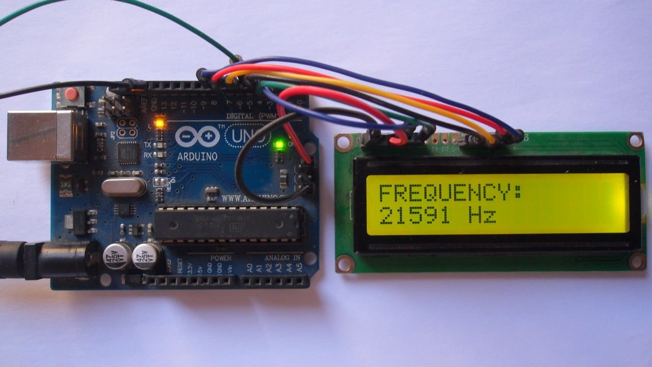
This post shows how to build a frequency counter device using Arduino UNO board where signal frequency value is displayed on 1602 LCD screen.
With this counter we can measure frequency of PWM signals with peak voltage of 5V.
Related Project:
220/380V AC Frequency Meter with Arduino
Hardware Required:
This is a list of all components required to build this project.
- Arduino UNO board —-> Atmega328P datasheet
- 16×2 LCD screen
- 330 ohm resistor
- 10k ohm variable resistor or potentiometer
- Breadboard
- Jumper wires
Arduino frequency counter circuit:
Project circuit diagram is shown below.
The 16×2 LCD screen (2 rows and 16 columns) is used to display the values of frequency and period of the input voltage where:
RS —> Arduino digital pin 2
E —> Arduino digital pin 3
D4 —> Arduino digital pin 4
D5 —> Arduino digital pin 6
D6 —> Arduino digital pin 7
D7 —> Arduino digital pin 8
VSS, RW, D0, D1, D2, D3 and K are connected to Arduino GND,
VEE to the 10k ohm variable resistor (or potentiometer) output,
VDD to Arduino 5V and A to Arduino 5V through 330 ohm resistor.
VEE pin is used to control the contrast of the LCD. A (anode) and K (cathode) are the back light LED pins.
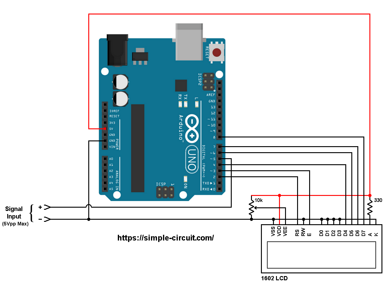
The PWM signal has two pins, let’s say positive (+) and negative (-), they are connected to the circuit as shown above.
The positive terminal is connected to Arduino digital pin 5 and the negative terminal is connected to Arduino GND pin.
Arduino frequency counter code
The following Arduino code requires a library which helps doing this project easily. This library is named FreqCount, it can be installed online through Arduino library manger (Manage Libraries…) or manually by downloading and installing its zip file. Download link is below:
Arduino FreqCount library —-> direct link
The FreqCount library uses Timer/Counter1 module to count number of pulses during fixed time, Timer/Counter2 module is used for this fixed time.
Full Arduino code:
1 2 3 4 5 6 7 8 9 10 11 12 13 14 15 16 17 18 19 20 21 22 23 24 25 26 27 28 29 30 31 32 33 34 35 36 37 38 | /************************************************************************* * * Arduino frequency counter. * This is a free software with NO WARRANTY. * https://simple-circuit.com/ * ************************************************************************/ #include <FreqCount.h> #include <LiquidCrystal.h> // include Arduino LCD library // LCD module connections (RS, E, D4, D5, D6, D7) LiquidCrystal lcd(2, 3, 4, 6, 7, 8); void setup(void) { // set up the LCD's number of columns and rows lcd.begin(16, 2); lcd.print("FREQUENCY:"); // initialize freqCount library with time basis of 1000ms (1 second) // Arduino counts number of pulses during period of 1 second FreqCount.begin(1000); } // main loop void loop() { if (FreqCount.available()) { unsigned long count = FreqCount.read(); lcd.setCursor(0, 1); lcd.print(count); // print frequency value in Hz lcd.print(" Hz "); } } // end of code. |
The video below shows a protoboard circuit of the project:
Discover more from Simple Circuit
Subscribe to get the latest posts sent to your email.


So it displays 50Hz all the time and counts nothing from my frequency generator.
I like these types of projects. I would have liked to see the hidden lower portion of your breadboard. And, I’d be interested to know what the minimum and maximum frequencies are available with this setup. From your video I see it can go up to about 1.003MHz. Can this device go down to 0 or 1Hz?
u dont measure the maximum frequency and the minimum
Hi, do you have the details for Adafruit Huzzah esp8266 for the FreqCountTimers.h
ie the details as for example the Duemilanove
// Arduino Duemilanove, Diecimila, LilyPad, Mini, Fio, etc
#elif defined(__AVR_ATmega328P__) || defined(__AVR_ATmega168__)
#define COUNTER_USE_TIMER1 // T1 is pin 5
#define TIMER_USE_TIMER2
Is this for dc or ac??
Yes, I will really appreciate some help on how to increase accuracy of 0.XX for low frequency events.
Best regards & thanks for the provided code, works very nice.
The counter works fine, but how to increase the accuracy of 0.XXX?
i tried it with Proteus, it doesn’t work. the lcd is okay, but suddenly the pulse from generator dissapear
Does anyone have an idea how to compare the previous measurement with the current one?
why you do not identify digit in pin
Actually there’s no need to define frequency input pin because the frequency library (FreqCount.h) uses Timer/Counter1 module of the ATmega328P microcontroller to calculate number of pulses during a predefined period, this means pulses source must be connected to Arduino UNO digital pin 5.
If you look at ATmega328P pin configuration then you may see (PCINT21/OC0B/T1) on pin RD5 (pin number 11).