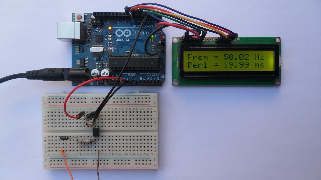
This project shows how to measure AC source frequency using Arduino UNO board where frequency and period values are printed on 1602 LCD screen.
This frequency counter can easily measure frequency of AC lines with voltages 110/220/380V – 50/60Hz.
No warranty is provided with this project, do it at your own risk!
Frequency is number of cycles (complete turns) per 1 second. Its main unit of measurement is Hertz (Hz).
Period is time required to complete 1 cycle (turn), its main unit is second.
Frequency = 1/Period.
Home alternating current (AC) frequency is 50 or 60Hz, most countries use 50Hz.
For frequency of 50Hz the period is 20 milliseconds and for 60Hz the period is about 16.67 milliseconds.
Hardware Required:
This is a list of all components required to build this project.
- Arduino UNO board —-> Atmega328P datasheet
- 16×2 LCD screen
- 330 ohm resistor
- 10k ohm variable resistor or potentiometer
- PC817 optocoupler —-> datasheet
- 120k ohm -2W resistor
- 10k ohm
- 1N4007 diode (or equivalent)
- Breadboard
- Jumper wires
Arduino frequency meter circuit:
Project circuit diagram is shown below.
The 16×2 LCD screen (2 rows and 16 columns) is used to display the values of frequency and period of the input voltage where:
RS —> Arduino digital pin 3
E —> Arduino digital pin 4
D4 —> Arduino digital pin 5
D5 —> Arduino digital pin 6
D6 —> Arduino digital pin 7
D7 —> Arduino digital pin 8
VSS, RW, D0, D1, D2, D3 and K are connected to Arduino GND,
VEE to the 10k ohm variable resistor (or potentiometer) output,
VDD to Arduino 5V and A to Arduino 5V through 330 ohm resistor.
VEE pin is used to control the contrast of the LCD. A (anode) and K (cathode) are the back light LED pins.
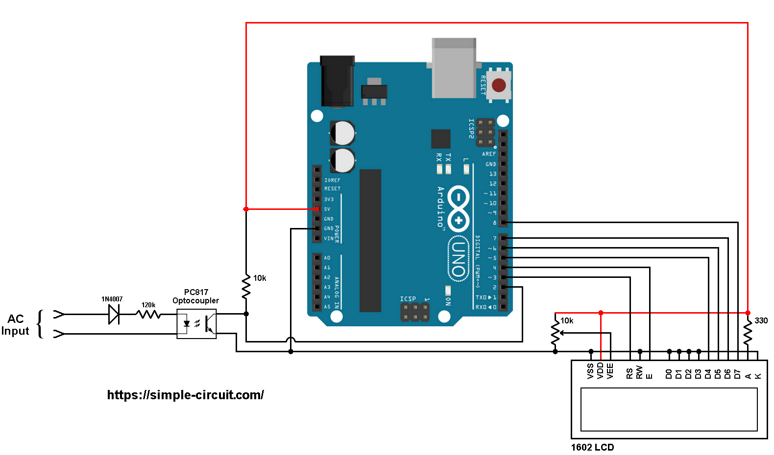
The AC input is connected to the circuit as shown where diode 1N4007 is used to eliminate negative half cycles because the PC817 optocoupler maximum reverse voltage is 6V.
The optocoupler is connected to AC main through 120k ohm resistor (and also the 1N4007 diode) which limits the current that passes through the optocoupler LED (IF).
With the 120k ohm resistor and with source of 220V, the peak forward current is equal to (neglecting diode voltages):
220x√2/120k = 2.59 mA and the RMS current (half wave) = 2.59/2 = 1.3 mA.
The output of the PC817 optocoupler is connected to the Arduino as follows:
The emitter is connected to Arduino GND,
The collector is connected to Arduino digital pin 2. This pin is also for external interrupt 0.
The collector is connected to Arduino +5V pin through pull up resistor of 10k ohm.
When the optocoupler LED is forward biased, its output is (transistor collector) is attached to GND (logic 0). During signal negative cycles the PC817 output is logic 1.
With the optocoupler high voltage side is isolated from low voltage side.
Arduino frequency meter code:
In this project I used external interrupt 0 to detect falling(going from high to low) of the optocoupler output. This interrupt is initialized as shown below:
1 2 | EIFR |= 1; // clear INT0 flag attachInterrupt(0, timer1_get, FALLING); // enable external interrupt (INT0) |
When there is an interrupt the Arduino directly executes the function timer1_get().
Measuring the frequency idea is simple, Timer1 module is used to measure time between 2 successive interrupts which means we have the time between 2 successive falling events. When the function timer1_get() is called, it stores Timer1 value on a variable named: tmr1.
Timer1 module is configured to increment by 2 every 1 microsecond (prescaler = 8) and its overflow interrupt is enabled in order to reset the variable tmr1 (helps when signal is removed).
With prescaler = 8, the clock input of Timer1 module is equal to: Timer1_CLK = 16MHz/8 = 2MHz.
With these configuration the lowest frequency that the Arduino can measure is about 31Hz.
Signal period:
Period (in us) = Timer1_Value/Timer1_CLK = Timer1_Value/16000000/8
Period(in us) = 8 x Timer1_Value/16000000
Period (in ms) = 8 x Timer1_Value/16000
Signal frequency:
Frequency = 1/Period
Frequency (in Hz) = 16000000/(8 x Timer1_Value)
Full Arduino code:
1 2 3 4 5 6 7 8 9 10 11 12 13 14 15 16 17 18 19 20 21 22 23 24 25 26 27 28 29 30 31 32 33 34 35 36 37 38 39 40 41 42 43 44 45 46 47 48 49 50 51 52 53 54 55 56 57 58 59 60 61 62 63 64 65 66 67 68 69 70 71 | /************************************************************************* * * Arduino frequency counter. * This is a free software with NO WARRANTY. * USE AT YOUR OWN RISK! * http://simple-circuit.com/ * ************************************************************************/ #include <LiquidCrystal.h> // include Arduino LCD library // LCD module connections (RS, E, D4, D5, D6, D7) LiquidCrystal lcd(3, 4, 5, 6, 7, 8); void setup(void) { lcd.begin(16, 2); // set up the LCD's number of columns and rows lcd.setCursor(0, 0); lcd.print("Freq ="); lcd.setCursor(0, 1); lcd.print("Peri ="); // Timer1 module configuration TCCR1A = 0; TCCR1B = 2; // enable Timer1 module with 1/8 prescaler ( 2 ticks every 1 us) TCNT1 = 0; // Set Timer1 preload value to 0 (reset) TIMSK1 = 1; // enable Timer1 overflow interrupt EIFR |= 1; // clear INT0 flag attachInterrupt(0, timer1_get, FALLING); // enable external interrupt (INT0) } uint16_t tmr1 = 0; float period, frequency; void timer1_get() { tmr1 = TCNT1; TCNT1 = 0; // reset Timer1 } ISR(TIMER1_OVF_vect) { // Timer1 interrupt service routine (ISR) tmr1 = 0; } // main loop void loop() { // save current Timer1 value uint16_t value = tmr1; // calculate signal period in milliseconds // 8.0 is Timer1 prescaler and 16000 = MCU_CLK/1000 period = 8.0 * value/16000; // calculate signal frequency which is = 1/period ; or = MCU_CLK/(Prescaler * Timer_Value) if(value == 0) frequency = 0; // aviod division by zero else frequency = 16000000.0/(8UL*value); lcd.setCursor(7, 0); lcd.print(frequency); lcd.print(" Hz "); // print period lcd.setCursor(7, 1); lcd.print(period); lcd.print(" ms "); delay(500); } // end of code. |
The video below shows a protoboard circuit of the project:
Related Project:
Arduino Frequency Counter | Arduino Projects
Discover more from Simple Circuit
Subscribe to get the latest posts sent to your email.


Thank you so much ????it’s working
Hi, I implemented your scketch and its working fine on genuine arduino uno, but on arduino mega 2560 on pin 21 with the same timer results are different. What I’m doing wrong? For example from Arduino Uno I obtain 49.99 .. 50.1 Hz and from Mega results are 50.37.. 50.5
Hello, I implemented this circuit on my arduino uno board but the frequency i obtained from the serial monitor is 0 Hz. The period is also 0 Hz. Please what could be wrong.
did you find out help me
Is your diode connected in the right direction?