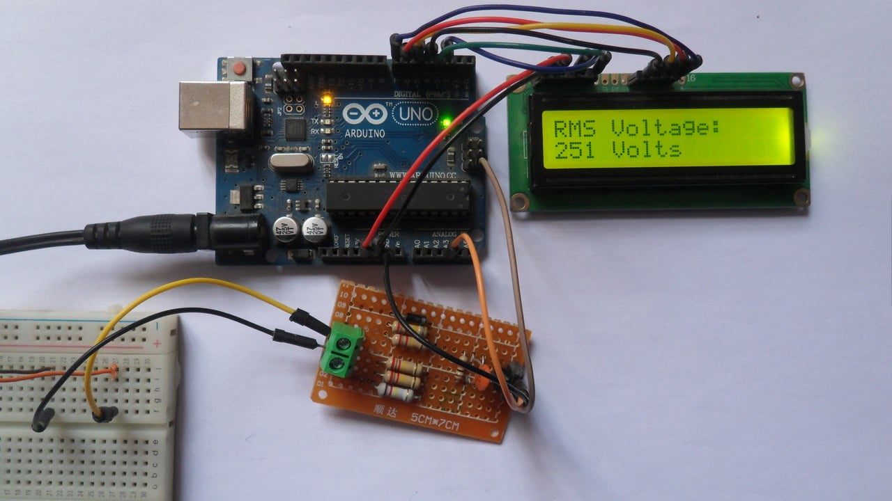
This post shows how to build a simple AC voltmeter that measure AC voltage with Arduino UNO board where voltage value is printed on 16×2 LCD screen.
This voltmeter can easily measure 110/220/380V AC voltages with frequency of 50 or 60Hz.
No warranty is provided with this project, do it at your own risk!
Hardware Required:
This is a list of all components required to build this project.
- Arduino UNO board —-> Atmega328P datasheet
- 16×2 LCD screen
- 330 ohm resistor
- 10k ohm variable resistor or potentiometer
- 4 x 220k ohm resistor
- 120k ohm resistor
- 1k ohm
- 100nF ceramic capacitor
- 1N4733A 5.1V Zener diode (or equivalent)
- 1N4007 diode (or equivalent)
- Breadboard
- Jumper wires
Arduino AC voltmeter circuit:
The image below shows project circuit diagram.
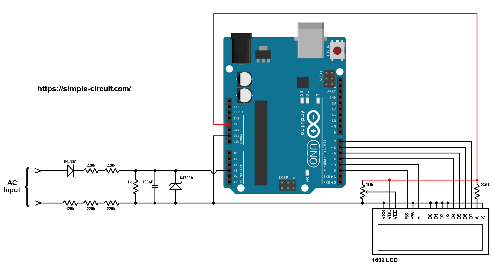
The AC input is connected to the circuit as shown where diode 1N4007 is used to eliminate the negative half cycles.
After we get the positive parts of the AC voltage signal, it enters to a voltage divider because the Arduino UNO board can’t deal with voltages higher than 5V. The voltage divider is composed of 4 x 220k ohm resistors, 1 x 120k ohm resistor and 1 x 1k ohm resistor, so the impedance of this voltmeter is about 1M ohm (mega-ohm).
The Arduino reads the voltage across the 1k ohm resistor which is equal to the input voltage divided by 1001k ohm (voltage divider equation).
So, if the input voltage is 220V then the voltage across the 1k ohm resistor is 0.220V = 220mV (RMS values).
The 100nF ceramic capacitor is used to stabilize and eliminate noise of voltage signal across the 1k resistor. The 1N4733A Zener diode (reverse-breakdown voltage is 5.1V) is used to protect the Arduino board from voltages higher than 5.1V.
The 16×2 LCD screen (2 rows and 16 columns) is used to display the value of the input voltage where:
RS —> Arduino digital pin 2
E —> Arduino digital pin 3
D4 —> Arduino digital pin 4
D5 —> Arduino digital pin 5
D6 —> Arduino digital pin 6
D7 —> Arduino digital pin 7
VSS, RW, D0, D1, D2, D3 and K are connected to Arduino GND,
VEE to the 10k ohm variable resistor (or potentiometer) output,
VDD to Arduino 5V and A to Arduino 5V through 330 ohm resistor.
VEE pin is used to control the contrast of the LCD. A (anode) and K (cathode) are the back light LED pins.
Arduino AC voltmeter code:
The following Arduino code measures the RMS value of the input AC voltage by detecting the maximum value of the half wave and then divide it by square root of 2 (√2).
So: Vrms = Vmax/√2
The Arduino detects the maximum value by reading analog voltage on channel 3 (A3) multiple times.
The function get_max() reads channel A3 voltage 100 times during period of more than 20ms (because for frequency of 50Hz the period is 20ms).
In this project the Arduino actually doesn’t give the True RMS of the input AC voltage because it uses the function: Vrms = Vmax/√2
That means the Arduino will give a correct measurement for a sine wave AC voltage input only!
Full Arduino code:
1 2 3 4 5 6 7 8 9 10 11 12 13 14 15 16 17 18 19 20 21 22 23 24 25 26 27 28 29 30 31 32 33 34 35 36 37 38 39 40 41 42 43 44 45 46 47 48 49 50 51 52 | /************************************************************************* * * AC Voltmeter with Arduino. * This is a free software with NO WARRANTY. * USE AT YOUR OWN RISK! * http://simple-circuit.com/ * ************************************************************************/ #include <LiquidCrystal.h> // include Arduino LCD library // LCD module connections (RS, E, D4, D5, D6, D7) LiquidCrystal lcd(2, 3, 4, 5, 6, 7); void setup(void) { lcd.begin(16, 2); // set up the LCD's number of columns and rows lcd.setCursor(0, 0); lcd.print("RMS Voltage:"); analogReference(INTERNAL); // set ADC positive reference voltage to 1.1V (internal) } // get maximum reading value uint16_t get_max() { uint16_t max_v = 0; for(uint8_t i = 0; i < 100; i++) { uint16_t r = analogRead(A3); // read from analog channel 3 (A3) if(max_v < r) max_v = r; delayMicroseconds(200); } return max_v; } // main loop void loop() { char buf[10]; // get amplitude (maximum - or peak value) uint32_t v = get_max(); // get actual voltage (ADC voltage reference = 1.1V) v = v * 1100/1023; // calculate the RMS value ( = peak/√2 ) v /= sqrt(2); sprintf(buf, "%03u Volts", v); lcd.setCursor(0, 1); lcd.print(buf); delay(100); } // end of code. |
The video below shows a protoboard circuit of the project:
And this one shows Proteus simulation:
Proteus simulation file download (use Proteus version 8.8 or higher to open it!):
Arduino AC voltmeter
Discover more from Simple Circuit
Subscribe to get the latest posts sent to your email.


I think this code is measuring the Rms value of the stepped down voltage at ADC pin, the actual voltage has to be calculated by considering the resistance values.
This project is very DANGEROUS!!! DO NOT apply practices described here. Never connect high voltage lines to a low voltage circuit.
This example provides a low cost non-isolated voltage measurement, the user should notice this before any hardware implementation.
For a galvanically isolated line voltage measurement consider this example:
AC Voltage & Frequency Measurement with Arduino
I tried to do it but the final value is never stable and it always changes from 120mV and likes changes to 220mV and so on. What’s wrong with the circuit above?
Nice project. A quick question. Can the 220R resistors be replaced by 10K ones or even 1M ones?
Hi , can we measure 400Ac voltage using this ? and can we use PC817 optocoupler for isolation ??
Hi Sir,
Can you provide the code for multiple voltage measuring Independent in single display
good projecket
Mine measures 154V instead of 220v I set in vsine properties. What am I doing wrong?
Hello!
Thank you for the project!
I would like to improve it. I wanna using it for generator to regulate it.
How can I to compare the measuring voltage with my INT chartacter?
Thank you!
Have a nice day!
The LM358 is standard Duel Operational Amplifier (OA) and does NOT provide any isolation (Galvanic or otherwise) that would make it suitable for this project. See my previous comments.
The LM358 data sheet can be found at https://www.ti.com/sitesearch/docs/universalsearch.tsp?searchTerm=LM358#q=LM358&t=everything&linkId=1
Re the question of measuring in 3 phase systems, it depends whether you are interested in the ‘phase – phase’ or ‘phase to neutral’ voltage, but the principle is still the same. In theory all 3 phases should be at the same voltage, but in practice there are slight variations though measuring one phase is usually sufficient for most purposes.
How to use it in three phase,
I think in case of galvanic isolation you should see a differential amplifier a simply lm358 would do the job
Good project pls i need the same project but with the pic16f877 mikroc or ccs c
This project is VERY DANGEROUS
NEVER connect mains level voltages direct to your projects. While this circuit will work (going by the comments) it incorporates a VERY DANGEROUS practice. Always use galvanic isolation like a transformer to isolate the mains supply from your projects – plug pack supplies are a good start as the dangerous mains voltages are contained within the ‘plug pack’ module. Be aware that using circuits that connect directly to can kill you if you make the smallest mistake in handling the project.
With the galvanic isolation in place, you will have no problems connecting the micro to your computer via the USB port.
I worked the electrical/electronics industry for over 30 years and was well aware of unsafe practices. Manufactures are also well aware of safety issues and go to great lengths to isolate the incoming mains voltages from the electronics in their devices and provide suitable insulation to ensure that it is impossible to touch any live part of the device.
A handy pocket tester with a neon bulb glows when you touch it to the mains with your finger touching the metal conductor on the back of your tester. If you remove you finger the glow stops. Essentially a mains current is flowing through our body to ground when you touch the tester conductor.
Is it unsafe?
Your 30 years experience hasn’t removed your fear towards “electricity kills”.
This project uses the same resistance value 1megOhm as in your tester. It is as “DANGEROUS” as your line tester…..!!!!
Provided we seldom touch it, even….
Thanks a lot. I followed the tutorial and it worked fine. Why did you use 600 (Amplitude) for Vsine? I’m aware that the AC Frequency is 50Hz.
Thanks.
How to check wave form of AC and plot it on screen
The other problem that I have is that when the circuit is not conected to the source, it still shows me values not equal to 0 on the LCD screen
What if I have an Arduino Mega? The “INTERNAL” configuration is not avaible in this product
Nevermind, for Mega is “INTERNAL1V1”
Hello,
Thank you for the project. What is the blue-lcd device part no. that you are demonstrating at the end of the video?
i tried it 12c lcd, but in my case lcd shows the value 777 Volts even no pin connected to the A3, i change the pin to A1, but the result is the same
thank u for your great work. please when i try using Arduino mega to run the code it does not run. any help
when you connect the usb port, the ground from your pc short circuits one of the tho inputs from the arduino because there is no galvanic isolation from the mains to your arduino. the shield on the USB is also the mains Ground
Yes you shouldn’t connect the Arduino to PC! The Arduino should be powered from another source (for example external battery).
Actually there’ll be no short circuit because there’s a resistor of 560k between the ground and mains line.
Can you please help me with measure of 3 fase
fase 1 on A1 fase 2 on A2 fase 3 on A3 . now i measure 366 volt on each channel of arduino instead 230volt
do i need extra resistor?
Hi
Thanks for this toturial… great work.
I followed it but without the lcd . i wanted to check the voltage from serial monitor.
the problem is that if use a multi-meter and take readings in the two ends of 1k resistor everything seems to work… when i am connecting it as you showing in the drawing to arduino ground then i can get no readings … it become zero
arduino monitors shows also zero
great tutorial can you please do ac ahmeter project