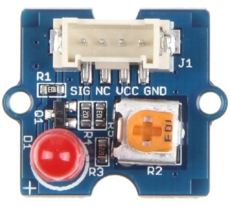
This Arduino example is for beginners, it shows how to make an LED blinking using Seeed Studio Grove LED socket kit which is shown below:

As shown in the Grove LED board there is a variable resistor of 10k ohm which is used to control the brightness of the LED.
We can easily change the color of the LED by replacing the red one with another with different color (yellow, white …).
This Grove board is compatible with 3.3V and 5V systems.
The LED socket kit is connected to Seeed Studio Base Shield via 4-pin Grove cable, the base shield is an add-on board that directly mounted to the Arduino/Genuino UNO board.
Hardware Required:
- Arduino/Genuino UNO board
- Grove base shield —> official page
- Grove LED socket kit —> official page
- Grove 4-pin cable
Arduino LED blink circuit:
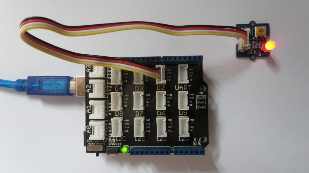
The following image shows the connection of the LED socket kit with the Grove base shield where a 4-pin wire is used to connect the two Grove modules.
Note that the base shield is directly mounted to the Arduino UNO board.
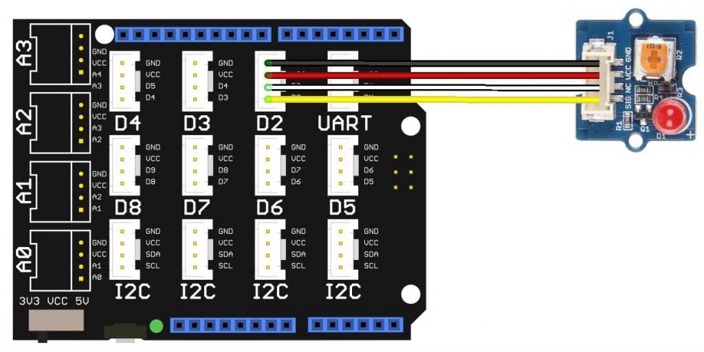
The following image shows a more detailed circuit diagram.
The Grove LED socket kit has 4 pins (GND, VCC, NC and SIG) where:
GND pin is connected to base shield GND and hence to Arduino GND,
VCC pin is connected to base shield VCC and hence to Arduino +5V pin,
NC (not connected) is not connected pin (using the 4-pin cable it looks as it is connected to base shield D3 pin),
SIG (signal) pin is connected to base shield D2 pin and hence to Arduino digital pin 2.
The Grove LED socket kit allows us to manually control the brightness of the LED with the 10k variable resistor (potentiometer).
Arduino LED blink circuit:
Example Arduino code is below.
1 2 3 4 5 6 7 8 9 10 11 12 13 14 15 16 17 18 19 20 21 22 23 | /************************************************************************* * * Arduino LED blink example with Seeed Studio Grove LED board. * This is a free software with NO WARRANTY. * https://simple-circuit.com/ * ************************************************************************/ #define LED 2 // define LED pin void setup(void) { pinMode(LED, OUTPUT); // configure LED pin as output } // main loop void loop() { digitalWrite(LED, HIGH); // turn LED on delay(500); // wait 500ms digitalWrite(LED, LOW); // turn LED off delay(500); // wait 500ms } // end of code. |
Arduino LED blink with Grove LED board video:
The following video shows hardware test circuit of this project where Arduino UNO board is equipped with Seeed Studio Grove base shield and Grove LED board is connected to the base shield via 4-pin wire connector.
Discover more from Simple Circuit
Subscribe to get the latest posts sent to your email.


