It is very easy to build a good and simple AC light dimmer using Arduino, this light dimmer is used to control the brightness of a simple 220V AC lamp. In this project I used the LM393 integrated circuit (dual comparator IC) for zero crossing detection of the AC voltage and BT136 triac which supplies the load (lamp) depending on the firing angle (alpha).
Related Projects:
The following two project may contain some useful information.
SCR control with Arduino – Half-wave controlled rectifier
Controlled bridge rectifier with Arduino
Components Required:
This is a list of the basic components needed to build this project.
- Arduino board
- BT136 Triac — datasheet
- 220V AC lamp
- LM393 (or LM339) comparator
- Optocoupler (MOC3020, MOC3021, MOC3022, MOC3023) — datasheet
- 2 x 1N4007 diode (or 1N4001)
- 2 x 220k ohm resistor
- 10k ohm potentiometer
- 10k ohm resistor
- 470 ohm resistor
- 120 ohm resistor
- 100 ohm resistor
- 0.01µF capacitor
- Breadboard
- Jumper wires
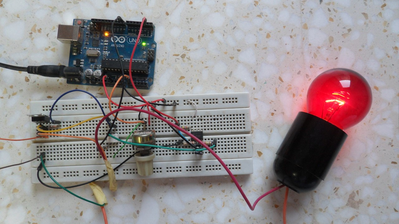
Arduino light dimmer circuit:
Project circuit schematic diagram is shown below.
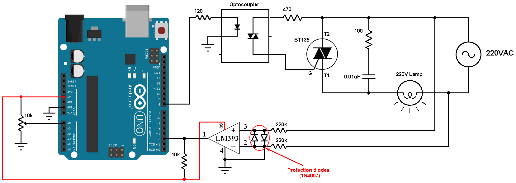
All grounded terminals are connected together.
In this project I used the LM393 (dual comparator IC) for the zero crossing detection, the LM339 quad comparator IC also can be used. An optocoupler can be used for the same purpose( zero crossing detection) but I think the comparator is much better. The two diodes which are connected between the non-inverting input (+) and the inverting input (-) of the comparator are used to limit the voltage across the 2 pins. The output of the LM393 (or LM339) is an open collector, so I added a 10k ohm resistor there (between +5V and arduino pin 2). Also the comparator chip is supplied with +5V which comes from the Arduino board.
The optocoupler (MOC302x) is used for firing the BT136 triac, its LED is connected to Arduino pin 8 through 120 ohm resistor. I chose the value 120 ohm in order to get a current of about 30mA (current passes through the optocoupler LED).
The 10k potentiometer is used to control the firing angle and therefore the brightness of the lamp.
Arduino light dimmer code:
The frequency of my AC source is 50Hz which means the period is 20ms, so the half wave period is 10ms = 10000µs.
The resolution of Arduino ADC module is 10-bit which means the digital value can vary between 0 and 1023.
I used Arduino interrupt (INT0 on pin 2) to detect the zero-crossing events, so when there is a zero crossing event (falling or rising), the Arduino interrupted and after some delay (angle alpha) it fires the triac.
1 2 3 4 5 6 7 8 9 10 11 12 13 14 15 16 17 18 19 20 21 22 23 24 25 26 27 28 29 30 31 32 33 34 35 | // Arduino light brightness control (light dimmer) code #define triac_gate 8 #define pot A0 bool ZC = 0; uint16_t alpha; void setup(void) { pinMode(triac_gate, OUTPUT); digitalWrite(triac_gate, LOW); attachInterrupt(0, ZC_detect, CHANGE); // Enable external interrupt (INT0) } void ZC_detect() { ZC = 1; } void loop() { if( ZC){ if(alpha < 9500) { delayMicroseconds(alpha); digitalWrite(triac_gate, HIGH); delayMicroseconds(200); digitalWrite(triac_gate, LOW); } ZC = 0; alpha = ( 1023 - analogRead(pot) ) * 10; if(alpha > 9500) alpha = 9500; } } |
Arduino light dimmer video:
Discover more from Simple Circuit
Subscribe to get the latest posts sent to your email.


excuse me, i just wanna ask about the alpha value. Can anyone explain about the “9500” value? like how the value affect the circuit?
Thank you ^^
explane for :delaymicroseconds(200);?why my lamp not stable….or blinking…
I have liked this project very much and i want to come up with it but i will be thankful if someone helps me with the block diagram and a flow chart of this project
can we replace lm393 with lm741?
tried with an lm358 and it work
what’s the different if we didn’t use LM393? because i read from the other blog, they didn’t use LM393
What is the purpose of the 100 ohm resistor and 0.01uF capacitor on the AC output? Can the circuit work without them?
That’s snubber circuit, it’s optional in this example!
hi, what is the voltage of the capacitor?
It can be 400V DC or 230V AC? Which one is correct =)
This is a ceramic capacitor (non polarized), you can easily find ones with 600V or higher (1kV …).
If you’ve a 400V one then you can use it!
Warning
This design may be very dangerous for people, because it does not isolate the part of high voltage (220 V AC) of the part of low voltage (5V DC).
The Arduino ground may be 220V relative to the AC installation ground.
When you apply 220V to 220k ohm resistor the current flows through it will be 1mA, you may not even feel it!
Also, the system should be grounded as our PCs should be, for example you’ll get shocked whenever you touch your PC if the outlet is not grounded.
That circuit is for zero-crossing detection, when you say isolation you may mean it’s better to use an optocoupler. I say the optocoupler will not give you a precise events for the zero crossing. for example let’s take the MOC3020 optocoupler, this device requires an input trigger current of at least 30mA (recommended is between 30 and 50mA), the question is what should be the value of the series resistor in order to guarantee the triggering of the device?
A better idea is adding a step down transformer with phase shift of 0° (for example from 220V to 6V), then the output of the transformer is connected to the comparator.
I have use this protect circuity for a long. https://imgur.com/a/w9qWmz9
I’ve build this circuit ,But it’s not controlling the brightness,when pot is get to 0 lamp off and increasing the pot bulb is on.what is the wrong ?
That means the Arduino may output logic high instead of pulses on pin 8 (triac_gate), you can check that using a simple multi-meter (or voltmeter), you should get voltage below 5V. Or:
Make sure that you’re using an appropriate optocoupler as the one used in the circuit (MOC3020, MOC3021 …).
what is the wattage of the bulb you use?
I think it’s 25W. You could use 60 or 100W …, but don’t use LED bulbs because they may not be dimmable!
what should be done in the code if the source is 220v 60 hz??
Approximately, no thing!
In Proteus software it shows the below error:
“Not able to simulate in real time.”
So kindly help me in solving the error in software as well as in hardware as it burns the 100 ohm resistor across the triac.
I had tried to implement this but 100 ohm resistor across the Triac gets burnt. While increasing the resistance it is not able to switch the bulb ON.
check the capacitor across triac