In the last Arduino project, I made a simple motor controller which controls the speed and direction of rotation of CD-ROM bipolar stepper motor. Now I’m going to show how to do the same thing with uinpolar stepper motor.
The stepper motor used in this example is 28BYJ-48 which usually comes with its driver board.
Related Projects:
Arduino Bipolar Stepper Motor Control
Stepper Motor Control with Arduino and Joystick
Basically there are two types of stepper motors: bipolar and unipolar. The bipolar stepper motor is a two-phase brushless motor which has two coils (windings), this motor has 4 wires (2 wires for each coil).
The other type is the unipolar stepper motor, it is 4-phase brushless motor which has 5 or 6 wires.
The popular controlling modes of of the stepper motor are: full step and half step. The full step can be divided into 2 types: one-phase and two-phase.
In full step one-phase mode the driver energizes one coil at a time. This type of controlling requires the least amount of power but provides the least torque.
In full step two-phase mode the driver energizes the two coils at the same time. This mode provides the highest torque but it requires twice as much power as one-phase mode.
Half step mode is a combination of the two full step modes (one-phase and two-phase). This mode increases accuracy by dividing each step by 2. it requires power in-between one-phase and two-phase modes, torque is also in-between.
There is another controlling type called microstepping, this type is more accurate than the half step mode, it requires two sinusoidal current sources with 90° shift.
In this example I’m going to use the full step two-phase mode for controlling the unipolar stepper motor.
Usually the unipolar stepper motor has 5 wires one for motor supply and the other for coils. This motor has 4 coils and they are connected as shown in the figure below:
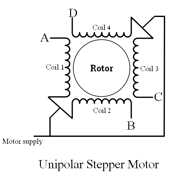
As shown in the above figure there are 4 coils: A, B, C and D. These coils has common point named in the figure Motor supply which is connected to positive terminal of power supply source. Other coil terminals are connected to a motor driver.
The unipolar stepper motor can be driven with L293D motor driver or ULN2003A Darlington transistor array IC. In this example I’m going to use the ULN2003A (or ULN2004) chip.
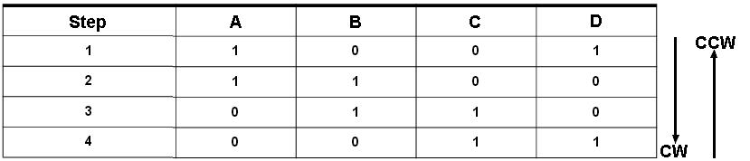
In the full step control mode always two windings are energized at the same time according to the following table where 1 means the coil is energized and 0 means not energized (both directions are shown):
Hardware Required:
- Arduino UNO board
- 28BYJ-48 unipolar stepper motor (with driver board)
- 10k ohm potentiometer
- Pushbutton
- 5V power source
- Bread board
- Jumper wires
Arduino uinpolar stepper motor control circuit:
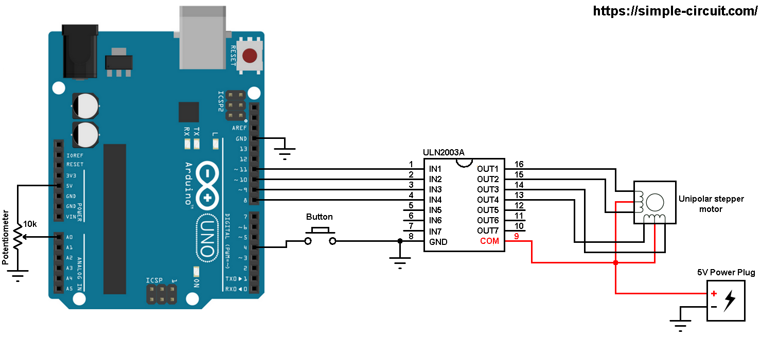
Example circuit diagram is shown below (all grounded terminals are connected together).
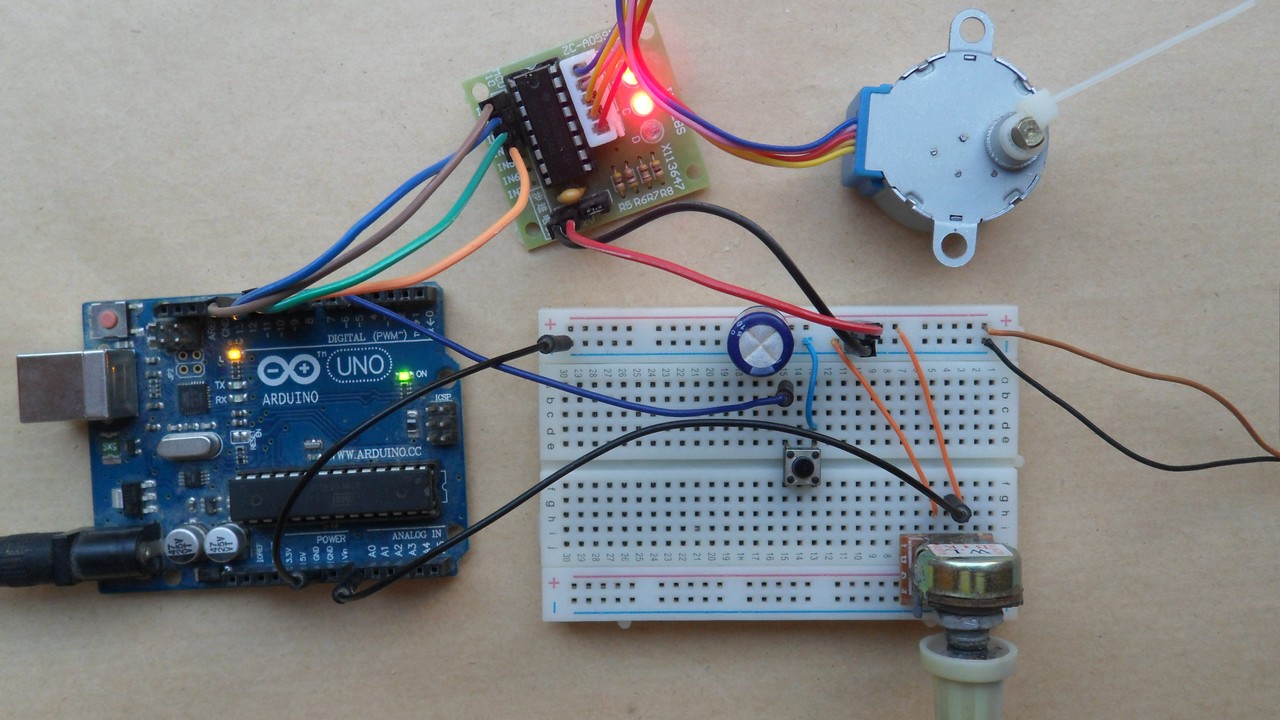
and the following image shows fritzing circuit:
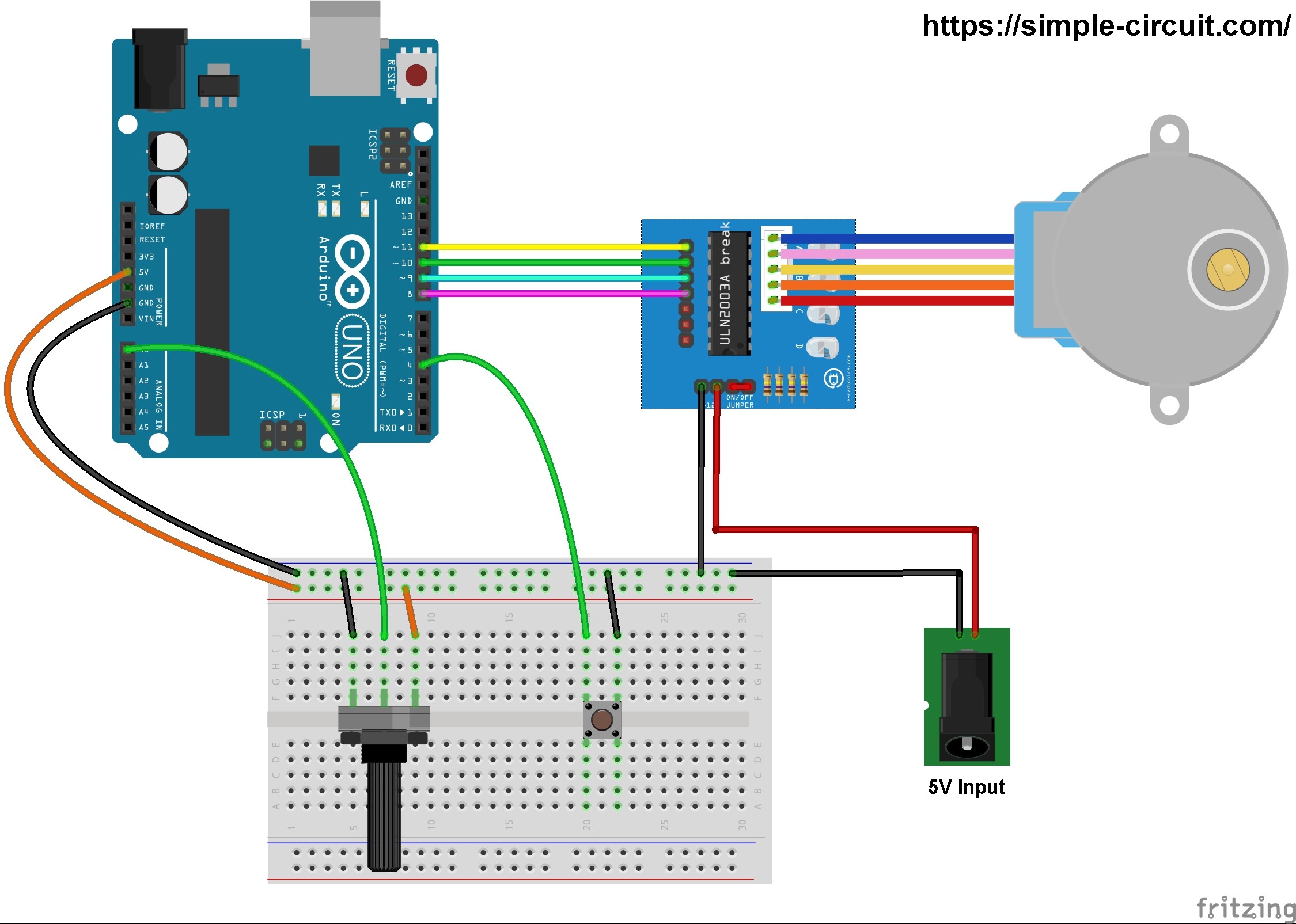
The stepper motor is connected to the ULN2003A board which is supplied with external power source of 5V. The control lines (IN1, IN2, IN3 and IN4) of this board are connected to the Arduino as follows:
IN1 to Arduino pin 11
IN2 to Arduino pin 10
IN3 to Arduino pin 9
IN4 to Arduino pin 8
The 10k ohm potentiometer is used to control the speed of the stepper motor, its output pin is connected to Arduino analog pin 0.
The push button which is connected to Arduino pin 4 is used to change the rotation direction of the stepper motor.
Arduino unipolar stepper motor control code:
In this example I used Arduino stepper motor library (built-in) which simplifies the code, it’s included in the code using the following line:
1 | #include <Stepper.h> |
The stepper motor which I used in this project is 28BYJ-48, this motor equipped with speed reducer of 1/64. The internal motor has 32 steps per one revolution which means the external shaft has 2048 steps per one revolution (64 x 32). Number of steps is defined in the code as shown below:
1 | #define STEPS 32 |
and the connection of the control lines of the stepper motor are defined as:
1 | Stepper stepper(STEPS, 8, 10, 9, 11); |
Using the function stepper.step(direction_) the stepper motor moves according to the variable direction_, in this example this variable may be 1 or -1. If direction_ = 1 the motor will move in the first direction and if direction_ = -1 the motor will move in the other direction.
When ever the pushbutton is pressed, the variable direction_ will be inverted (1 or -1).
Rest of code is described through comments.
1 2 3 4 5 6 7 8 9 10 11 12 13 14 15 16 17 18 19 20 21 22 23 24 25 26 27 28 29 30 31 32 33 34 35 36 37 38 39 40 41 42 43 44 45 46 47 48 49 50 51 52 53 54 55 56 57 58 59 60 61 62 63 64 65 66 67 | /* * Unipolar stepper motor speed and direction control with Arduino. * Full step control. * This is a free software with NO WARRANTY. * http://simple-circuit.com/ */ // include Arduino stepper motor library #include <Stepper.h> // change this to the number of steps on your motor #define STEPS 32 // create an instance of the stepper class, specifying // the number of steps of the motor and the pins it's // attached to Stepper stepper(STEPS, 8, 10, 9, 11); const int button = 4; // direction control button is connected to Arduino pin 4 const int pot = A0; // speed control potentiometer is connected to analog pin 0 void setup() { // configure button pin as input with internal pull up enabled pinMode(button, INPUT_PULLUP); } int direction_ = 1, speed_ = 0; void loop() { if ( digitalRead(button) == 0 ) // if button is pressed if ( debounce() ) // debounce button signal { direction_ *= -1; // reverse direction variable while ( debounce() ) ; // wait for button release } // read analog value from the potentiometer int val = analogRead(pot); // map digital value from [0, 1023] to [2, 500] // ===> min speed = 2 and max speed = 500 rpm if ( speed_ != map(val, 0, 1023, 2, 500) ) { // if the speed was changed speed_ = map(val, 0, 1023, 2, 500); // set the speed of the motor stepper.setSpeed(speed_); } // move the stepper motor stepper.step(direction_); } // a small function for button debounce bool debounce() { byte count = 0; for(byte i = 0; i < 5; i++) { if (digitalRead(button) == 0) count++; delay(10); } if(count > 2) return 1; else return 0; } |
The following video shows a simple hardware circuit of the project:
Discover more from Simple Circuit
Subscribe to get the latest posts sent to your email.


I see a capacitor between power and ground in the photo, but it is not in the parts list. What does it do and what size is it?
Thanks for posting this, it was very helpful in getting me started using stepper motors.