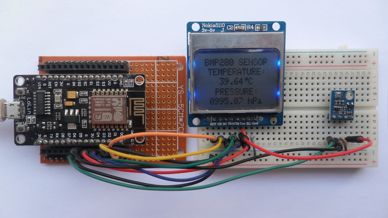
This post shows how to interface ESP8266 NodeMCU Wi-Fi board (ESP12-E module) with BMP280 barometric pressure and temperature sensor.
The NodeMCU reads temperature & pressure values from the BMP280 sensor and prints them (respectively in °C and hPa) on Nokia 5110 LCD display (84×48 pixel).
To see how to interface NodeMCU board with Nokia 5110 LCD, visit this post:
Interfacing ESP8266 NodeMCU with Nokia 5110 LCD
About the BMP280 sensor:
The BMP280 sensor from Bosch Sensortec is a low cost pressure and temperature sensor with good accuracy. Because pressure changes with altitude we can use it as an altimeter with ±1 meter accuracy (pressure accuracy = ±1 hPa). Some parameters of the sensor are listed below:
Pressure range: 300…1100 hPa (equivalent to +9000…-500m above/below sea level)
Pressure resolution: 0.01 hPa ( < 10 cm)
Temperature range: -40…85 °C
Temperature resolution: 0.01 °C
Interface: I2C and SPI
Hardware Required:
- ESP8266 NodeMCU development board
- Nokia 5110 LCD module
- BMP280 sensor module —-> datasheet
- micro USB cable (for programming and powering the circuit)
- Breadboard
- Jumper wires
NodeMCU with BMP280 sensor and Nokia 5110 LCD circuit:
Project circuit schematic diagram is shown below.
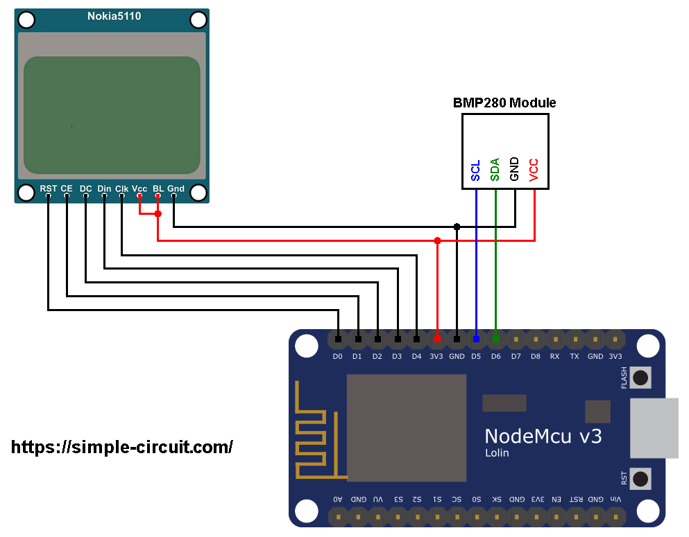
Generally, the BMP280 sensor module has at least 4 pins because it can work in SPI mode or I2C mode. For the I2C mode we need 4 pins: VCC, GND, SDA and SCL where:
GND (ground) is connected to NodeMCU GND pin,
VCC is the supply pin which is connected to NodeMCU 3V3 pin,
SDA is I2C bus serial data line, connected to NodeMCU pin D6 (GPIO12),
SCL is I2C bus serial clock line, connected to NodeMCU pin D5 (GPIO14).
The Nokia 5110 LCD which is shown in the circuit diagram has 8 pins (from left to right): RST (reset), CE (chip enable), DC (or D/C: data/command), Din (data in), Clk (clock), VCC (3.3V), BL (back light) and Gnd (ground).
The Nokia 5110 LCD is connected to the NodeMCU board as follows:
RST (reset) pin is connected to pin D0 (ESP8266EX GPIO16),
CE (chip enable) pin is connected to pin D1 (ESP8266EX GPIO5),
DC (data/command) pin is connected to pin D2 (ESP8266EX GPIO4),
DIN (data in) pin is connected to pin D3 (ESP8266EX GPIO0),
CLK (clock) pin is connected to pin D4 (ESP8266EX GPIO2),
VCC and BL are connected to pin 3V3,
GND is connected to pin GND.
NodeMCU with BMP280 sensor and Nokia 5110 LCD code:
The following Arduino code requires 3 libraries from Adafruit Industries:
The first library is a driver for the Nokia 5110 LCD (PCD8544 controller), download link is below:
Adafruit Nokia 5110 LCD library
The 2nd library is Adafruit graphics library which can be downloaded from the following link
Adafruit graphics library —-> direct link
The third library is for the BMP280 sensor:
Adafruit BMP280 Library —-> direct link
You may need to install Adafruit Unified Sensor library if it’s not already installed, download link is below:
Adafruit Unified Sensor library —-> direct link
After the download, go to Arduino IDE —> Sketch —> Include Library —> Add .ZIP Library … and browse for the .zip file (previously downloaded).
The same thing for the other library files.
Hints:
In the code there are total of 4 libraries, they’re included in the code as follows:
1 2 3 4 | #include <Wire.h> // include Wire library (required for I2C devices) #include <Adafruit_GFX.h> // include Adafruit graphics library #include <Adafruit_PCD8544.h> // include Adafruit PCD8544 (Nokia 5110) library #include <Adafruit_BMP280.h> // include Adafruit BMP280 sensor library |
As any other I2C device, the BMP280 sensor has an I2C slave address which may be 0x76 or 0x77. This address depends on the connection of the SDO pin (used for SPI mode as serial data out or MISO), if the SDO pin is connected (directly or through resistor) to VCC (3.3V) the address will be 0x77, and if it’s connected to GND the address will be 0x76.
The default I2C address of the BMP280 library is defined as 0x77 and my device I2C address is 0x76.
In the code, the definition of the I2C slave address and the initialization of its library are shown below:
1 2 3 4 | // define device I2C address: 0x76 or 0x77 (0x77 is library default address) #define BMP280_I2C_ADDRESS 0x76 // initialize Adafruit BMP280 library Adafruit_BMP280 bmp280; |
The initialization of the BMP280 sensor is done using the function begin() which returns 1 if OK and 0 if error. In the code the initialization with the previously defined address is as shown below:
1 | bmp280.begin(BMP280_I2C_ADDRESS) |
Reading the values of temperature and pressure:
1 2 3 | // read temperature and pressure from the BMP280 sensor float temp = bmp280.readTemperature(); // get temperature float pressure = bmp280.readPressure(); // get pressure |
Note that the BMP280 sensor library returns the value of the pressure in Pa unit and to convert it to hPa we’ve to divide it by 100.
1 bar = 10000 Pa = 100 hPa. ( 1 hPa = 100 Pa = 1 millibar)
Pa: Pascal
hPa: hectoPascal
Temperature and pressure values are displayed on the SSD1306 OLED screen.
If there is a problem with the BMP280 sensor (for example wrong device address) the screen will display Connection Error!
Full Arduino Code:
1 2 3 4 5 6 7 8 9 10 11 12 13 14 15 16 17 18 19 20 21 22 23 24 25 26 27 28 29 30 31 32 33 34 35 36 37 38 39 40 41 42 43 44 45 46 47 48 49 50 51 52 53 54 55 56 57 58 59 60 61 62 63 64 65 66 67 68 69 70 71 72 73 74 75 76 77 78 79 80 81 82 83 | /************************************************************************** * * ESP8266 NodeMCU with Nokia 5110 LCD (84x48 Pixel) and BMP280 barometric * pressure & temperature sensor. * This is a free software with NO WARRANTY. * http://simple-circuit.com/ * *************************************************************************/ #include <Wire.h> // include Wire library (required for I2C devices) #include <Adafruit_GFX.h> // include Adafruit graphics library #include <Adafruit_PCD8544.h> // include Adafruit PCD8544 (Nokia 5110) library #include <Adafruit_BMP280.h> // include Adafruit BMP280 sensor library // Nokia 5110 LCD module connections (CLK, DIN, D/C, CS, RST) Adafruit_PCD8544 display = Adafruit_PCD8544(D4, D3, D2, D1, D0); // define device I2C address: 0x76 or 0x77 (0x77 is library default address) #define BMP280_I2C_ADDRESS 0x76 // initialize Adafruit BMP280 library Adafruit_BMP280 bmp280; void setup(void) { // initialize the display display.begin(); Wire.begin(D6, D5); // set I2C pins [SDA = D6, SCL = D5], default clock is 100kHz // you can change the contrast around to adapt the display // for the best viewing! display.setContrast(50); display.clearDisplay(); // clear the screen buffer display.setTextSize(1); display.setTextColor(BLACK, WHITE); display.setCursor(3, 0); display.print("BMP280 SENSOR"); display.display(); if ( !bmp280.begin(BMP280_I2C_ADDRESS) ) { // connection error! display.setCursor(0, 15); display.println("Connection"); display.print("error!"); display.display(); while(1) // stay here delay(1000); } display.setCursor(7, 10); display.print("TEMPERATURE:"); display.setCursor(16, 31); display.print("PRESSURE:"); display.display(); } // main loop void loop() { // get temperature and pressure from library float temp = bmp280.readTemperature(); // get temperature float pressure = bmp280.readPressure(); // get pressure // print data on the LCD screen // 1: print temperature display.setCursor(15, 20); if(temp < 0) display.printf("-%02u.%02u C", (int)abs(temp) % 100, (int)(abs(temp) * 100) % 100 ); else display.printf(" %02u.%02u C", (int)temp % 100, (int)(temp * 100) % 100 ); display.drawRect(53, 20, 3, 3, BLACK); // print degree symbol ( ° ) // 2: print pressure display.setCursor(9, 41); display.printf("%04u.%02u hPa", (int)(pressure/100), (int)((uint32_t)pressure % 100) ); // now update the screen display.display(); delay(2000); // wait 2 seconds } // end of code. |
Discover more from Simple Circuit
Subscribe to get the latest posts sent to your email.

Very helpful, thanks