This tutorial shows how to interface ESP8266 NodeMCU (ESP-12E) board with ST7789 TFT display.
The ST7789 TFT module contains a display controller with the same name: ST7789. It’s a color display that uses SPI interface protocol and requires 3, 4 or 5 control pins, it’s low cost and easy to use.
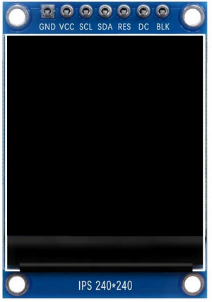
This display is an IPS display, it comes in different sizes (1.3″, 1.54″ …) but all of them should have the same resolution of 240×240 pixel, this means it has 57600 pixels. This module works with 3.3V only and it doesn’t support 5V.
TFT: Thin-Film Transistor.
SPI: Serial Peripheral Interface.
IPS: In-Plane Switching.
The following image shows a ST7789 display module provided by Adafruit Industries:

Another version of the ST7789 display module is shown below. This one has no CS (chip select) pin, its internally attached to GND:
Project Hardware Required:
- NodeMCU board
- ST7789 TFT display module (1.3″, 1.54″ …)
- Micro USB cable (for programming and powering the whole circuit)
- Breadboard
- Jumper wires

NodeMCU with ST7789 TFT Display Circuit:
Project circuit schematic diagram is shown below.
The ST7789 display module shown in project circuit diagram has 7 pins: (from right to left): GND (ground), VCC, SCL (serial clock), SDA (serial data), RES (reset), DC (or D/C: data/command) and BLK (back light).
Connecting the BLK pin is optional. The back light turns off when the BLK pin connected to the ground (GND).

The ST7789 TFT display module is connected to the NodeMCU board as follows:
GND is connected to pin GND of the NodeMCU board,
VCC and BL are connected to pin 3V3,
SCL pin is connected to D5 (ESP8266EX GPIO14),
SDA pin is connected to D7 (ESP8266EX GPIO13),
RES pin is connected to D2 (ESP8266EX GPIO4),
DC pin is connected to D1 (ESP8266EX GPIO5).
If the display module has a CS pin (Chip Select) then it should be connected to NodeMCU pin D8 (GPIO15).
Pins D5 (GPIO14) and D7 (GPIO13) are hardware SPI module pins of the ESP8266EX microcontroller respectively for SCK (serial clock) and MOSI (master-out slave-in).
NodeMCU with ST7789 TFT Display Code:
The Arduino code below requires two libraries from Adafruit Industries:
The first library is a driver for the ST7789 TFT display which can be installed from Arduino IDE library manager (Sketch —> Include Library —> Manage Libraries …, in the search box write “st7789” and install the one from Adafruit).
The second library is Adafruit graphics library which can be installed also from Arduino IDE library manager.
Both libraries can be installed manually, first download them from the following 2 links:
Adafruit ST7789 TFT library —-> direct link
Adafruit graphics library —-> direct link
After the download, go to Arduino IDE —> Sketch —> Include Library —> Add .ZIP Library … and browse for the .zip file (previously downloaded).
The same thing for the other library file.
Hints:
The 2 library files are included in the main code as shown below.
1 2 | #include <Adafruit_GFX.h> // Core graphics library #include <Adafruit_ST7789.h> // Hardware-specific library for ST7789 |
The ST7789 TFT module pins (CS, RST and DC) connections are defined as shown below:
1 2 3 4 | // ST7789 TFT module connections #define TFT_DC D1 // TFT DC pin is connected to NodeMCU pin D1 (GPIO5) #define TFT_RST D2 // TFT RST pin is connected to NodeMCU pin D2 (GPIO4) #define TFT_CS D8 // TFT CS pin is connected to NodeMCU pin D8 (GPIO15) |
The other display pins (SDA and SCL) are connected to NodeMCU hardware SPI pins (respectively D7 and D5).
The Adafruit ST7789 library is initialized with this line:
1 2 | // Initialize Adafruit ST7789 TFT library Adafruit_ST7789 tft = Adafruit_ST7789(TFT_CS, TFT_DC, TFT_RST); |
And the TFT display is initialized using the following command:
1 2 | // if the display has CS pin try with SPI_MODE0 tft.init(240, 240, SPI_MODE2); // Init ST7789 display 240x240 pixel |
The display may not work if it has a CS pin, try with SPI_MODE0 which is the default mode of the library or just use: tft.init(240, 240);
Rest of code is described through comments.
Full Arduino code:
1 2 3 4 5 6 7 8 9 10 11 12 13 14 15 16 17 18 19 20 21 22 23 24 25 26 27 28 29 30 31 32 33 34 35 36 37 38 39 40 41 42 43 44 45 46 47 48 49 50 51 52 53 54 55 56 57 58 59 60 61 62 63 64 65 66 67 68 69 70 71 72 73 74 75 76 77 78 79 80 81 82 83 84 85 86 87 88 89 90 91 92 93 94 95 96 97 98 99 100 101 102 103 104 105 106 107 108 109 110 111 112 113 114 115 116 117 118 119 120 121 122 123 124 125 126 127 128 129 130 131 132 133 134 135 136 137 138 139 140 141 142 143 144 145 146 147 148 149 150 151 152 153 154 155 156 157 158 159 160 161 162 163 164 165 166 167 168 169 170 171 172 173 174 175 176 177 178 179 180 181 182 183 184 185 186 187 188 189 190 191 192 193 194 195 196 197 198 199 200 201 202 203 204 205 206 207 208 209 210 211 212 213 214 215 216 217 218 219 220 221 222 223 224 225 226 227 228 229 230 231 232 233 234 235 236 237 238 239 240 241 242 243 244 245 246 247 248 249 250 251 252 253 254 255 256 257 258 259 260 261 262 263 264 265 266 267 268 269 270 271 272 273 274 275 276 277 278 279 280 281 282 283 284 285 286 287 288 289 290 291 292 293 294 295 296 297 298 299 300 301 302 303 304 305 | /************************************************************************** * * Interfacing ESP8266 NodeMCU with ST7789 TFT display (240x240 pixel). * Graphics test example. * This is a free software with NO WARRANTY. * https://simple-circuit.com/ * *************************************************************************/ /************************************************************************** This is a library for several Adafruit displays based on ST77* drivers. Works with the Adafruit 1.8" TFT Breakout w/SD card ----> http://www.adafruit.com/products/358 The 1.8" TFT shield ----> https://www.adafruit.com/product/802 The 1.44" TFT breakout ----> https://www.adafruit.com/product/2088 as well as Adafruit raw 1.8" TFT display ----> http://www.adafruit.com/products/618 Check out the links above for our tutorials and wiring diagrams. These displays use SPI to communicate, 4 or 5 pins are required to interface (RST is optional). Adafruit invests time and resources providing this open source code, please support Adafruit and open-source hardware by purchasing products from Adafruit! Written by Limor Fried/Ladyada for Adafruit Industries. MIT license, all text above must be included in any redistribution *************************************************************************/ #include <Adafruit_GFX.h> // Core graphics library #include <Adafruit_ST7789.h> // Hardware-specific library for ST7789 // ST7789 TFT module connections #define TFT_DC D1 // TFT DC pin is connected to NodeMCU pin D1 (GPIO5) #define TFT_RST D2 // TFT RST pin is connected to NodeMCU pin D2 (GPIO4) #define TFT_CS D8 // TFT CS pin is connected to NodeMCU pin D8 (GPIO15) // initialize ST7789 TFT library with hardware SPI module // SCK (CLK) ---> NodeMCU pin D5 (GPIO14) // MOSI(DIN) ---> NodeMCU pin D7 (GPIO13) Adafruit_ST7789 tft = Adafruit_ST7789(TFT_CS, TFT_DC, TFT_RST); float p = 3.1415926; void setup(void) { Serial.begin(9600); Serial.print(F("Hello! ST77xx TFT Test")); // if the display has CS pin try with SPI_MODE0 tft.init(240, 240, SPI_MODE2); // Init ST7789 display 240x240 pixel // if the screen is flipped, remove this command tft.setRotation(2); Serial.println(F("Initialized")); uint16_t time = millis(); tft.fillScreen(ST77XX_BLACK); time = millis() - time; Serial.println(time, DEC); delay(500); // large block of text tft.fillScreen(ST77XX_BLACK); testdrawtext("Lorem ipsum dolor sit amet, consectetur adipiscing elit. Curabitur adipiscing ante sed nibh tincidunt feugiat. Maecenas enim massa, fringilla sed malesuada et, malesuada sit amet turpis. Sed porttitor neque ut ante pretium vitae malesuada nunc bibendum. Nullam aliquet ultrices massa eu hendrerit. Ut sed nisi lorem. In vestibulum purus a tortor imperdiet posuere. ", ST77XX_WHITE); delay(1000); // tft print function! tftPrintTest(); delay(4000); // a single pixel tft.drawPixel(tft.width()/2, tft.height()/2, ST77XX_GREEN); delay(500); // line draw test testlines(ST77XX_YELLOW); delay(500); // optimized lines testfastlines(ST77XX_RED, ST77XX_BLUE); delay(500); testdrawrects(ST77XX_GREEN); delay(500); testfillrects(ST77XX_YELLOW, ST77XX_MAGENTA); delay(500); tft.fillScreen(ST77XX_BLACK); testfillcircles(10, ST77XX_BLUE); testdrawcircles(10, ST77XX_WHITE); delay(500); testroundrects(); delay(500); testtriangles(); delay(500); mediabuttons(); delay(500); Serial.println("done"); delay(1000); } void loop() { tft.invertDisplay(true); delay(500); tft.invertDisplay(false); delay(500); } void testlines(uint16_t color) { tft.fillScreen(ST77XX_BLACK); for (int16_t x=0; x < tft.width(); x+=6) { tft.drawLine(0, 0, x, tft.height()-1, color); delay(0); } for (int16_t y=0; y < tft.height(); y+=6) { tft.drawLine(0, 0, tft.width()-1, y, color); delay(0); } tft.fillScreen(ST77XX_BLACK); for (int16_t x=0; x < tft.width(); x+=6) { tft.drawLine(tft.width()-1, 0, x, tft.height()-1, color); delay(0); } for (int16_t y=0; y < tft.height(); y+=6) { tft.drawLine(tft.width()-1, 0, 0, y, color); delay(0); } tft.fillScreen(ST77XX_BLACK); for (int16_t x=0; x < tft.width(); x+=6) { tft.drawLine(0, tft.height()-1, x, 0, color); delay(0); } for (int16_t y=0; y < tft.height(); y+=6) { tft.drawLine(0, tft.height()-1, tft.width()-1, y, color); delay(0); } tft.fillScreen(ST77XX_BLACK); for (int16_t x=0; x < tft.width(); x+=6) { tft.drawLine(tft.width()-1, tft.height()-1, x, 0, color); delay(0); } for (int16_t y=0; y < tft.height(); y+=6) { tft.drawLine(tft.width()-1, tft.height()-1, 0, y, color); delay(0); } } void testdrawtext(char *text, uint16_t color) { tft.setCursor(0, 0); tft.setTextColor(color); tft.setTextWrap(true); tft.print(text); } void testfastlines(uint16_t color1, uint16_t color2) { tft.fillScreen(ST77XX_BLACK); for (int16_t y=0; y < tft.height(); y+=5) { tft.drawFastHLine(0, y, tft.width(), color1); } for (int16_t x=0; x < tft.width(); x+=5) { tft.drawFastVLine(x, 0, tft.height(), color2); } } void testdrawrects(uint16_t color) { tft.fillScreen(ST77XX_BLACK); for (int16_t x=0; x < tft.width(); x+=6) { tft.drawRect(tft.width()/2 -x/2, tft.height()/2 -x/2 , x, x, color); } } void testfillrects(uint16_t color1, uint16_t color2) { tft.fillScreen(ST77XX_BLACK); for (int16_t x=tft.width()-1; x > 6; x-=6) { tft.fillRect(tft.width()/2 -x/2, tft.height()/2 -x/2 , x, x, color1); tft.drawRect(tft.width()/2 -x/2, tft.height()/2 -x/2 , x, x, color2); } } void testfillcircles(uint8_t radius, uint16_t color) { for (int16_t x=radius; x < tft.width(); x+=radius*2) { for (int16_t y=radius; y < tft.height(); y+=radius*2) { tft.fillCircle(x, y, radius, color); } } } void testdrawcircles(uint8_t radius, uint16_t color) { for (int16_t x=0; x < tft.width()+radius; x+=radius*2) { for (int16_t y=0; y < tft.height()+radius; y+=radius*2) { tft.drawCircle(x, y, radius, color); } } } void testtriangles() { tft.fillScreen(ST77XX_BLACK); int color = 0xF800; int t; int w = tft.width()/2; int x = tft.height()-1; int y = 0; int z = tft.width(); for(t = 0 ; t <= 15; t++) { tft.drawTriangle(w, y, y, x, z, x, color); x-=4; y+=4; z-=4; color+=100; } } void testroundrects() { tft.fillScreen(ST77XX_BLACK); int color = 100; int i; int t; for(t = 0 ; t <= 4; t+=1) { int x = 0; int y = 0; int w = tft.width()-2; int h = tft.height()-2; for(i = 0 ; i <= 16; i+=1) { tft.drawRoundRect(x, y, w, h, 5, color); x+=2; y+=3; w-=4; h-=6; color+=1100; } color+=100; } } void tftPrintTest() { tft.setTextWrap(false); tft.fillScreen(ST77XX_BLACK); tft.setCursor(0, 30); tft.setTextColor(ST77XX_RED); tft.setTextSize(1); tft.println("Hello World!"); tft.setTextColor(ST77XX_YELLOW); tft.setTextSize(2); tft.println("Hello World!"); tft.setTextColor(ST77XX_GREEN); tft.setTextSize(3); tft.println("Hello World!"); tft.setTextColor(ST77XX_BLUE); tft.setTextSize(4); tft.print(1234.567); delay(1500); tft.setCursor(0, 0); tft.fillScreen(ST77XX_BLACK); tft.setTextColor(ST77XX_WHITE); tft.setTextSize(0); tft.println("Hello World!"); tft.setTextSize(1); tft.setTextColor(ST77XX_GREEN); tft.print(p, 6); tft.println(" Want pi?"); tft.println(" "); tft.print(8675309, HEX); // print 8,675,309 out in HEX! tft.println(" Print HEX!"); tft.println(" "); tft.setTextColor(ST77XX_WHITE); tft.println("Sketch has been"); tft.println("running for: "); tft.setTextColor(ST77XX_MAGENTA); tft.print(millis() / 1000); tft.setTextColor(ST77XX_WHITE); tft.print(" seconds."); } void mediabuttons() { // play tft.fillScreen(ST77XX_BLACK); tft.fillRoundRect(25, 10, 78, 60, 8, ST77XX_WHITE); tft.fillTriangle(42, 20, 42, 60, 90, 40, ST77XX_RED); delay(500); // pause tft.fillRoundRect(25, 90, 78, 60, 8, ST77XX_WHITE); tft.fillRoundRect(39, 98, 20, 45, 5, ST77XX_GREEN); tft.fillRoundRect(69, 98, 20, 45, 5, ST77XX_GREEN); delay(500); // play color tft.fillTriangle(42, 20, 42, 60, 90, 40, ST77XX_BLUE); delay(50); // pause color tft.fillRoundRect(39, 98, 20, 45, 5, ST77XX_RED); tft.fillRoundRect(69, 98, 20, 45, 5, ST77XX_RED); // play color tft.fillTriangle(42, 20, 42, 60, 90, 40, ST77XX_GREEN); } |
Interfacing ESP8266 NodeMCU with ST7789 TFT Video:
The video below shows a simple hardware test circuit for NodeMCU board with ST7789 display.
Discover more from Simple Circuit
Subscribe to get the latest posts sent to your email.

Hi there
I am using a ST7789 without a CS pin…For the line of code:-
” #define TFT_CS D8 ”
Should I still leave it as defined connected to D8 pin?
Ohhh Yeah….I forgot to mention that the display did not show anything even the code was uploaded without any errors from the output screen.
Works perfectly on Wemos D1 mini too. Thank you very much !
Thank you!
This works hassle-free with
tft.init(240, 240, SPI_MODE2);
to me
“If the display module has a CS pin (Chip Select) then it should be connected to NodeMCU pin D8 (GPIO15).”
This did not work for me. In fact when I connected these, the IDE could not connect to the 8266. Instead, I connected TCS (TFT CS) to GND and then it worked.
Thanks to your tutorial you save the live of two 240×240 Displays ST7789 displays, that I first Itended to throw away because of the the not working SPI Bus.
First I use the Aduino example Adafruit ST7735 and ST7789 Library / graficstest in the original.
This test is absolutly useles!! Because no one tells you that you have to use the SPI Mode 2 to use an LCD without an CS Pin ! tft.init(240, 240, SPI_MODE2)
Now it work for me.
Best regards Car
In my project, I’m using a nodemcu with MPU6050 using the I2C interface which uses the D1 and D2 pins respectively
.I want to use a LCD display such that it will have a small size which can be used on a device which is to be wore on the wrist. And to use less number of wires I was thinking of SPI interfacing for it .
I just want to display the time constantly and reminders for some tasks at the set intervals.
Which display would you like to suggest me for this application?
And if i’m using the D1 and D2 pins with MPU sensor, which pins can I use for the SPI interfacing of the LCD where you have used D1 and D2 in the above code.
Please suggest.
Thank you!
thanks for your post, it’s helps me a lot to make my ESP8266 work . all is working fine 🙂
have you an example to show a picture or a libraty that i can use to show a sprite or a .jpg for example