Today, most robotic projects are based on DC motors where speed and direction of rotation of this type of motors are controlled with the help of a driver circuit such as the DRV8833. The DRV8833 is a motor driver IC (integrated circuit) from Texas Instruments commonly used in robotic projects. It is designed to control the speed and direction of two DC motors and can handle a voltage range of 2.7V to 10.8V. The DRV8833 is a dual H-bridge driver, which means it can control two motors independently.
The DRV8833 is capable of driving motors with a peak current of 2A and a continuous RMS current of 1.5A per H-Bridge (PWP and RTY Package Options). It also includes built-in protection features such as short-circuit protection, overcurrent protection, overtemperature protection, and undervoltage lockout.
As an addition to DC motors, the DRV8833 can drive two DC brush motors, a bipolar stepper motor, solenoids, or other inductive loads.
To use the DRV8833 in a robotic project, we need to connect it to a microcontroller such as an Arduino or a Raspberry Pi. The microcontroller will send commands to the DRV8833 to control the speed and direction of the motors.
This tutorial shows how to control speed and direction of rotation of two robot car DC motors using Arduino board and DRV8833 module, a two potentiometers connected to the Arduino board are used to set speed and direction of the two motors.
The DRV8833 board with pinout used in this project is shown below:
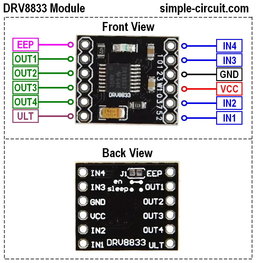
The DRV8833 module has a simple pinout with 12 pins. Here is a brief description of each pin:
- VCC: This is the positive power supply pin. It should be connected to the positive terminal of the power source.
- GND: This is the ground pin. It should be connected to the negative terminal of the power source.
- EEP: Latest three letters of the word SLEEP, this pin puts the DRV8833 in sleep mode when it is connected to ground (logic low)
- ULT: Latest three letters of the word FAULT, this is the fault output pin of the DRV8833, it outputs a logic low when the chip in fault condition (overtemperature, overcurrent).
- IN1: Bridge A input 1 – Logic input controls state of OUT1.
- IN2: Bridge A input 2 – Logic input controls state of OUT2.
- IN3: Bridge B input 1 – Logic input controls state of OUT3.
- IN4: Bridge B input 2 – Logic input controls state of OUT4.
- OUT1: Bridge A output 1
- OUT2: Bridge A output 2
- OUT3: Bridge B output 1
- OUT4: Bridge B output 2
DRB8833 Module Circuit Schematic Diagram:
The DRV8833 module circuit schematic diagram is shown below:
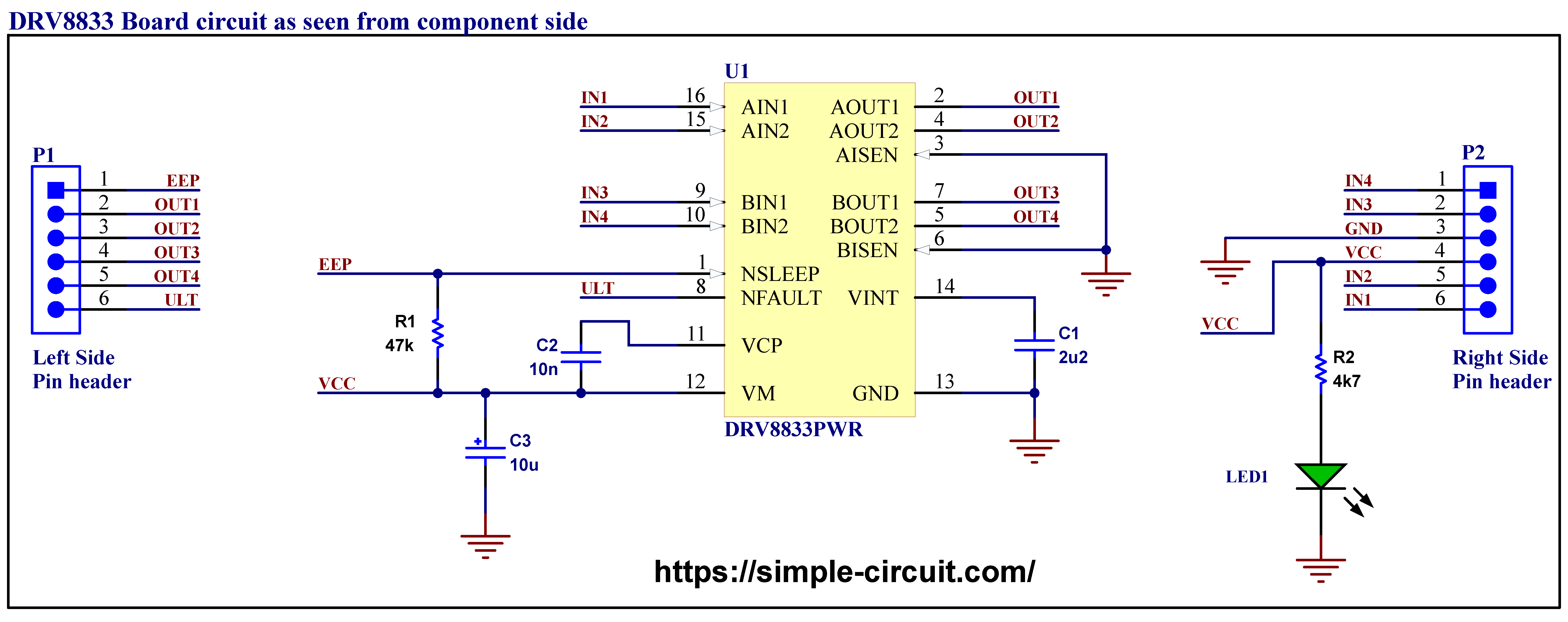
As you can see the module circuit is very simple, it is based on the DRV8833 IC, 3 capacitors, 2 resistors, one LED, and 2 pin headers. To keep the DRV8833 in normal working mode the EEP pin (SLEEP) is connected to VCC through a 47k resistor and to put the chip in sleep mode just connect it to the ground.
When a DC motor is connected to the DRV8833 board the control of motor direction is done according to the following table:
| IN1 / IN3 | IN2 / IN4 | OUT1 / OUT3 | OUT2/ OUT4 | Function |
| 0 | 0 | High Impedance | High Impedance | Coast/fast decay |
| 0 | 1 | Low | High | Reverse |
| 1 | 0 | High | Low | Forward |
| 1 | 1 | Low | Low | Brake/slow decay |
The speed of the motor can be controlled by sending a Logic Low to one control input (for example IN1) and PWMing the 2nd input (IN2).
Interfacing Arduino with DRV8833 Dual Motor Driver Module:
As we’ve the DRV8833 module, building project hardware circuit is very simple, only few wires are required. Project complete circuit diagram is shown below:
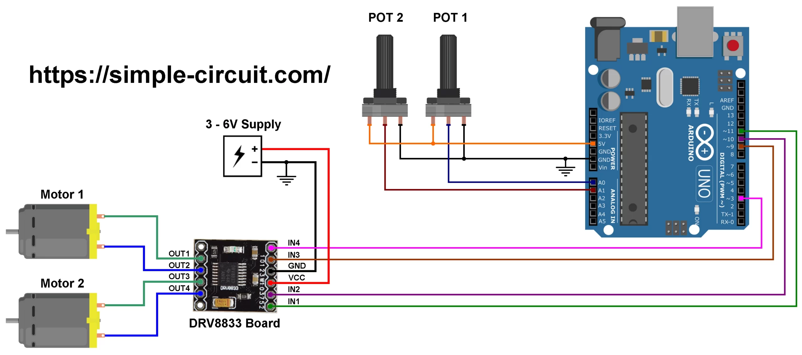
The motors used in this project are just the motors used in robot car, they are DC motor type with nominal voltage of 6V.
Motor1 terminals are connected to OUT1 & OUT2 of the DRV8833 module and Motor2 terminals are connected to OUT3 & OUT4. The DRV8833 module is supplied with external power source of 6V, we can use lower voltage such as 5V or even 3V, it is recommended not to use the 5V from the Arduino board or from Laptop USB because they may not provide sufficient current to properly supply the two motors.
A two potentiometers connected to the Arduino board are used to set speed and direction of the two motors. POT1 output is connected to Arduino analog channel 0 (A0) is used to control speed and direction of rotation of Motor 1. POT2 output is connected to Arduino analog channel 1 (A1) is used to control speed and direction of rotation of Motor 2.
It is clear that each Arduino used pin can generate PWM signal, this allows us to control speed of the two motors in the forward and reverse directions.
To see how this circuit works just watch the video at the end of the tutorial.
Hardware required:
This is a summary of project required parts.
- Arduino UNO or equivalent board such as Arduino Nano, Mini (U2) —> ATmega328P datasheet
- DRV8833 Module —> DRV8833 datasheet
- 2 x Robot car DC motor with rated voltage of 6V
- 2 x 10k Potentiometer
- Power supply with voltage 3 – 6V
- Bread board & jumper wires
Interfacing Arduino with DRV8833 Dual Motor Driver Module Code:
The full Arduino code of our project is the one below.
The connection between the Arduino board and the DRV8833 module is defined as shown below:
1 2 3 4 5 6 | #define POT1 A0 #define POT2 A1 #define IN1 11 #define IN2 10 #define IN3 9 #define IN4 3 |
Rest of code is described through comments.
1 2 3 4 5 6 7 8 9 10 11 12 13 14 15 16 17 18 19 20 21 22 23 24 25 26 27 28 29 30 31 32 33 34 35 36 37 38 39 40 41 42 43 44 45 46 47 48 49 50 51 52 53 54 55 56 57 58 59 60 61 62 63 64 65 | /************************************************************************************** * Two DC motor control using Arduino and DRV8833 dual H-bridge motor driver. * There are 2 potentiometers connected to the Arduino, each one control speed and * direction of rotation of 1 motor. * This is a free software with NO WARRANTY. * http://simple-circuit.com/ /**************************************************************************************/ #define POT1 A0 #define POT2 A1 #define IN1 11 #define IN2 10 #define IN3 9 #define IN4 3 // the setup function runs once when you press reset or power the board void setup() { // make all motor control pins low digitalWrite(IN1, LOW); digitalWrite(IN2, LOW); digitalWrite(IN3, LOW); digitalWrite(IN4, LOW); // configure all motor control pins as outputs pinMode(IN1, OUTPUT); pinMode(IN2, OUTPUT); pinMode(IN3, OUTPUT); pinMode(IN4, OUTPUT); } // main loop function void loop() { int16_t mot1 = analogRead(POT1) / 2; // read analog voltage from POT 1 int16_t mot2 = analogRead(POT2) / 2; // read analog voltage from POT 2 // motor 1 control if( mot1 > 255) { mot1 = mot1 - 256; analogWrite(IN1, mot1); digitalWrite(IN2, LOW); } else { mot1 = 255 - mot1; analogWrite(IN2, mot1); digitalWrite(IN1, LOW); } // motor 2 control if( mot2 > 255) { mot2 = mot2 - 256; analogWrite(IN3, mot2); digitalWrite(IN4, LOW); } else { mot2 = 255 - mot2; analogWrite(IN4, mot2); digitalWrite(IN3, LOW); } delay(500); // wait half a second } // end of code. |
Finally, the following video shows my simple DIY circuit of this project where Arduino NANO board is used.
Discover more from Simple Circuit
Subscribe to get the latest posts sent to your email.


