The TM1637 module is a popular 4-digit seven-segment LED display module that is commonly used with Arduino boards for displaying numeric data. It communicates with the Arduino board using a two-wire interface (CLK and DIO) and can display numbers, letters, and a few special characters.
This module is a pre-built board that basically includes the TM1637 driver IC and a 4-digit seven-segment LED display.
TM1637 Driver IC features:
The TM1637 display module has several features that make it useful for a variety of applications, including:
- Low power consumption: The driver IC can operate at a low voltage of 3.3V and has a low power consumption (typical operating voltage is always 5V), making it suitable for battery-powered applications.
- Built-in oscillator: The TM1637 has a built-in RC oscillator that can generate a signal for the display without requiring an external crystal or clock source.
- Brightness control: The TM1637 has a built-in 8-level brightness control function that can be adjusted through software.
- Flexible interface: The two-wire interface used by the TM1637 is simple and easy to use, allowing it to be connected to a variety of microcontrollers.
The TM1637 is commonly used in various applications such as digital clocks, timers, and scoreboards. Its simplicity and ease of use make it a popular choice for hobbyists and makers. Additionally, there are many libraries and code examples available for using this type of display with various microcontrollers, making it easy to get started with.
This tutorial shows how to interface the Arduino board with the TM1637 4-digit seven-segment display module, just an incremented number is printed on the display. We’ll see also Proteus simulation of this project.
TM1637 Module Pinout:
The TM1637 module used in this project is shown below:
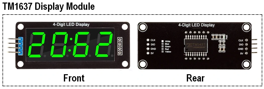
The TM1637 module has a total of 4 pins, which include the following:
- VCC: This pin is connected to the positive terminal of the power supply, typically 5V.
- GND: This pin is connected to the ground.
- DIO: This pin is connected to a digital pin on the Arduino board and used for data signal input/output.
- CLK: This pin is connected to a digital pin on the Arduino board and used for clock signal input.
Note that the pinout can vary slightly between different models or manufacturers of the TM1637 module. It is always a good idea to refer to the datasheet or documentation provided by the manufacturer for the specific module you are using.
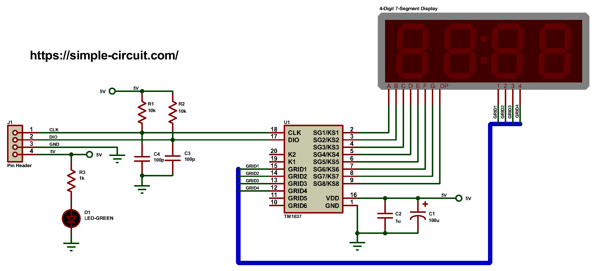
TM1637 Module Circuit Schematic Diagram:
The circuit diagram of the TM1637 module is very simple, the basic components are the TM1637 IC and the 4-digit 7-segment display, there are also 4 SMD capacitors and 3 SMD resistors and 1 SMD LED (Light-Emitting Diode). Circuit schematic diagram of the TM1637 display module is shown below.
Interfacing TM1637 4-Digit 7-Segment Display with Arduino:
Project circuit schematic diagram is the one below.
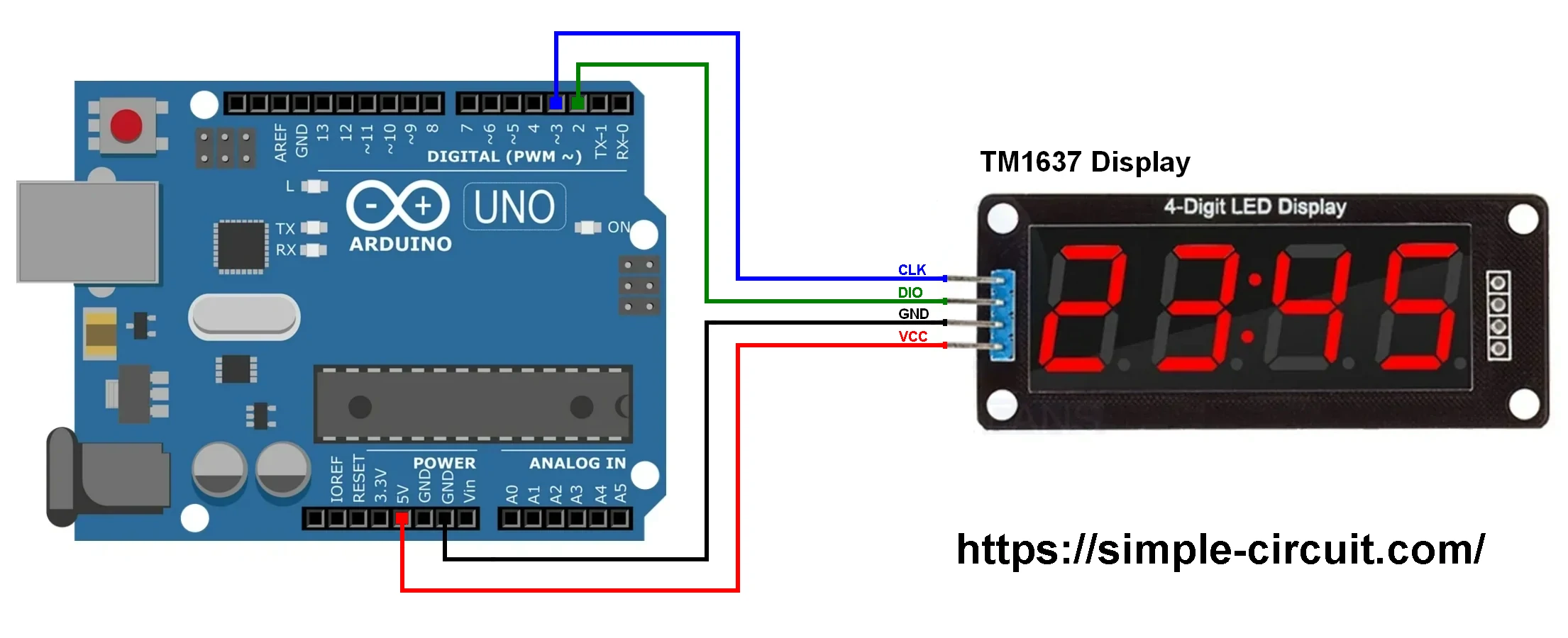
Project circuit diagram is very simple as shown, only 4 wires are required to connect the Arduino uno board with the TM1637 display module.
The TM1637 module is connected to the Arduino board as follows:
- CLK pin of the TM1637 to Arduino digital pin 3.
- DIO pin of the TM1637 to Arduino digital Pin 2.
- GND pin of the TM1637 to Arduino GND pin.
- VCC pin of the TM1637 to Arduino 5V pin.
Hardware required:
This is a summary of project required parts.
- Arduino UNO or equivalent board such as Arduino Nano, Mini (U2) —> ATmega328P datasheet
- TM1637 display module —> TM1637 IC datasheet
- Jumper wires
Interfacing TM1637 4-Digit 7-Segment Display with Arduino Code:
Firstly, we need to install the TM1637 display module library using Arduino IDE Library Manager, in the search filter box write “TM1637” and install the one written by ‘Avishay Orpaz’. The same library GitHub link is the one below:
TM1637 Module Arduino Library
After installing the library, it’s included in the Arduino as:
1 2 | // include TM1637 display module library #include <TM1637Display.h> |
And the TM1637 display module pins are defined in the Arduino code as:
1 2 3 | // define TM1637 Module connection pins #define CLK 3 // clock pin #define DIO 2 // data pin |
Rest of code is described through comments.
1 2 3 4 5 6 7 8 9 10 11 12 13 14 15 16 17 18 19 20 21 22 23 24 25 26 27 28 29 30 31 32 33 34 35 36 37 38 | /****************************************************************************** * Interfacing TM1637 4-Digit seven segment display module with Arduino. * This example shows how print an incremented number on the TM1637 display from 0 to 9999. * This is a free software with NO WARRANTY. * https://simple-circuit.com/ /*******************************************************************************/ // include TM1637 display module library #include <TM1637Display.h> // define TM1637 Module connection pins #define CLK 3 // clock pin #define DIO 2 // data pin // initialize TM1637 display module library TM1637Display display(CLK, DIO); void setup() { // set display brightness (7 maximum brightness and 0 minimum) display.setBrightness(7); } uint16_t i = 0; void loop() { // print variable 'i' on the display (decimal format with leading zeros) display.showNumberDec(i, true); i++; // increment 'i' if(i > 9999) i = 0; delay(1000); } // end of code. |
The following video shows my simple DIY circuit of this project where Arduino NANO board is used.
Interfacing TM1637 4-Digit 7-Segment Display with Arduino Proteus Simulation:
The interfacing of the Arduino board with the 4-digit display module can be easily simulated using Proteus simulation software as shown in this video:
Arduino with TM1637 module Proteus simulation file download:
Proteus simulation file of this project can be downloaded from the below Google Drive link.
DOWNLOAD
Discover more from Simple Circuit
Subscribe to get the latest posts sent to your email.


Bad library file – TM1637Display – original UNO cannot use.