In some applications it is important to measure ambient light level using a light sensor, for example our smartphone automatically adjusts its display brightness according to the lighting condition around us. Another example is that for better growth, plants require a certain amount of light for photosynthesis, a light sensors can be used to monitor light levels in greenhouses and indoor gardens to ensure that plants receive optimal light levels.
An ambient light sensor is a device that detects the amount of light in the environment and provides an output that corresponds to the light level. Ambient light sensors are used in a variety of applications, including smart homes, lighting control systems, agriculture, and display brightness control.
One commonly used integrated ambient light sensor is the TSL2591 sensor from ams-OSRAM USA INC, which uses a combination of photodiodes and signal processing circuitry to provide accurate and reliable light level measurements. The TSL2591 ambient light sensor can be easily interfaced with an Arduino board or any other microcontroller.
This Arduino tutorial shows how to interface the TSL2591 sensor with Arduino board where light intensity (in lux) is printed on a 1602 LCD screen and sent to Arduino IDE Serial Monitor tool.
The TSL2591 Ambient Light Level Sensor Module:
The TSL2591 module is a sensor module that mainly contains the TSL2591 digital light sensor and associated circuitry. The module typically includes a breakout board with a small printed circuit board (PCB) that includes the sensor chip, power regulation circuitry, and an I2C level converter interface for a proper communication with a wide range of microcontrollers and electronic development boards.
The TSL2591 module used in this tutorial is the one shown below:
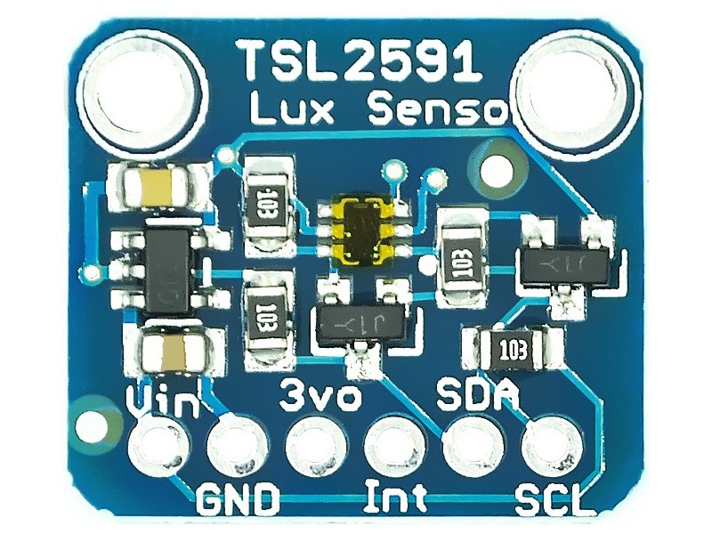
This module is similar to the one provided by Adafruit Industries (TSL2591 Module REV-A).
The main component of the TSL2591 module is the TSL2591 chip (TSL25911FN). The TSL2591 is a very high sensitivity digital light sensor that can measure the intensity of ambient light. It is a sensor that combines two photodiodes on a single CMOS integrated circuit with different spectral responses to provide accurate and reliable measurements in a wide range of lighting conditions.
TSL2591 Sensor Features:
- High sensitivity to 188µLux.
- 600M:1 dynamic range
- Wide dynamic range: The sensor can detect light levels from 188 µlux to 88,000 lux, providing accurate measurements in a wide range of lighting conditions.
- Integrated ADC: This sensor contains two integrated ADC that convert the analog photodiode currents into a digital output which represents the irradiance measured on each channel.
- I2C interface: The TSL2591 sensor uses an I2C interface to communicate with the master device, making it easy to communicate with microcontrollers and electronic development boards such as the Arduino.
- Programmable interrupt function: The interrupt pin can be used to signal the microcontroller when the light levels exceed a certain programmable threshold.
- Wide working temperature range from -30 to 70 °C.
TSL2591 Module Pinout:
The TSL2591 module typically has the following pinout as written in module PCB:
- VIN: This pin is used to provide power to the module.
- GND: This pin is connected to ground.
- 3VO: This is the 3.3V output from the module built-in voltage regulator, it can source up to 100mA.
- INT: This pin is an optional interrupt pin, which can be used to signal the microcontroller when the light levels exceed a certain threshold.
- SDA: This pin is used for the I2C serial data line, which is used to transmit data between the TSL2591 module and the microcontroller.
- SCL: This pin is used for the I2C serial clock line, which is used to synchronize data transfer between the TSL2591 module and the microcontroller.
The pinout may vary slightly between different TSL2591 module manufacturers, so it’s important to check the module’s datasheet or documentation to confirm the pinout before connecting it to an Arduino board or other microcontroller.
TSL2591 Module Circuit Diagram:
The circuit schematic diagram of the TSL2591 module is given below.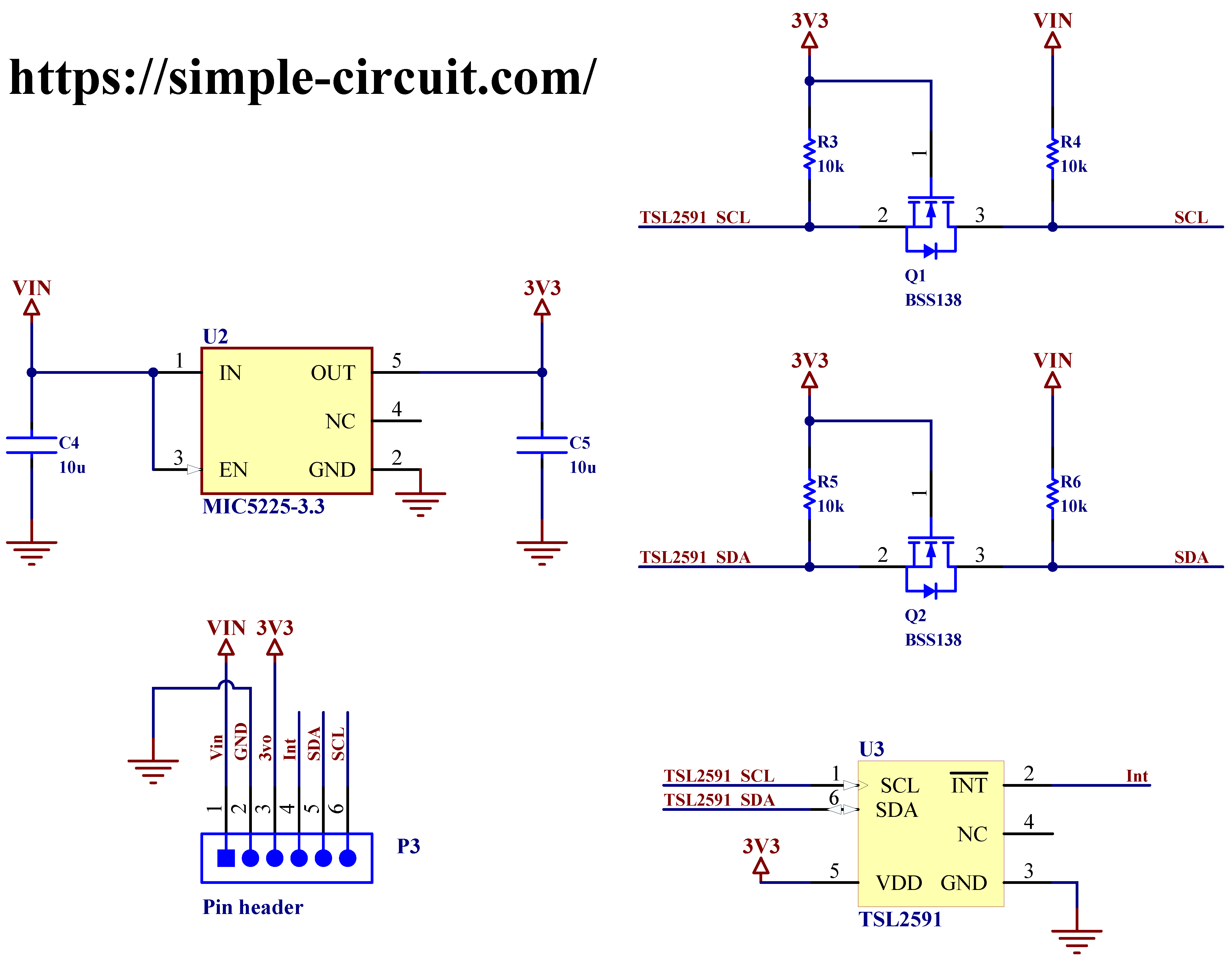
The main component of the TSL2591 module is the TSL2591 sensor chip (TSL25911FN), this chip works with voltage range between 2.7V and 3.6V (typical 3V). The module includes a LDO voltage regulator MIC5225-3.3 from Microchip that supplies the TSL2591 sensor chip with regulated voltage of 3.3V from input of 5V.
The module also includes a bidirectional I2C level shifter which allows a proper I2C communication between the TSL2591 chip (operating at 3.3V) and the master device such as the Arduino UNO microcontroller (operating at 5V). If the whole system circuit including the master device works with 3.3V then the I2C level shifter will have no effect. This I2C level shifter consists of two BSS138 N-Channel MOSFET and four 10k resistors.
Interfacing TSL2591 Ambient Light Sensor with Arduino Circuit:
Project circuit schematic diagram is shown below.
I drew project circuit diagram using Fritzing software, I hope it’s clear and understandable!
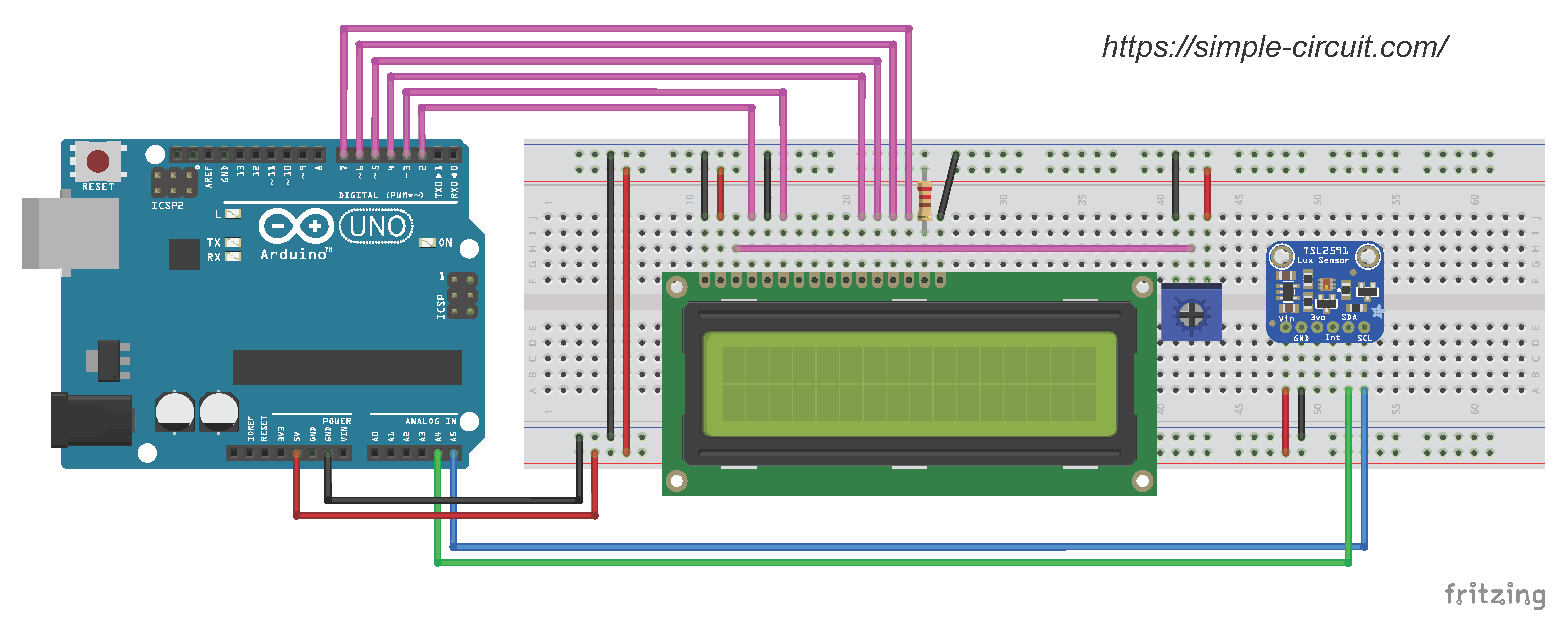
Circuit connection is very simple as we have the TSL2591 module, it is connected to the Arduino board through the breadboard as follows:
- VIN pin of the TSL2591 module is connected to 5V pin of the Arduino board.
- GND pin of the TSL2591 module is connected to GND pin of the Arduino board.
- SDA pin of the TSL2591 module is connected to A4 pin of the Arduino board.
- SCL pin of the TSL2591 module is connected to A5 pin of the Arduino board.
Note that A4 & A5 pins of the Arduino board are hardware Two-Wire Interface (TWI) pins of the board microcontroller (ATmega328P) .
Hardware required:
This is a summary of project required parts.
- Arduino UNO or equivalent board such as Arduino Nano, Mini… —> ATmega328P datasheet
- TSL2591 module —> TSL2591 datasheet
- 1602 LCD screen
- 10k variable resistor, or potentiometer
- 220 Ohm resistor
- Breadboard & some jumper wires
Interfacing TSL2591 Ambient Light Sensor with Arduino Code:
To be able to compile & upload the Arduino code we need to install the TSL2591 library, we can do this by going to:
Sketch menu —> Include Library —> Manage Libraries. In the Library Manager, search for “TSL2591” and install the Adafruit TSL2591 library.
Library GitHub link is the one below:
Adafruit Library for TSL2591 Module
During the online installation of the library, Arduino IDE may ask for installing another libraries from Adafruit also, such as Adafruit Unified Sensor Driver.
Programming hints:
All the used libraries are included in the Arduino code as given below:
1 2 3 4 | #include <LiquidCrystal.h> // Include Arduino LCD library #include <Wire.h> // Include Arduino wire library (required for any I2C device) #include <Adafruit_Sensor.h> // Include Adafruit Unified Sensor Driver #include "Adafruit_TSL2591.h" // Include Adafruit TSL2591 library |
The LCD and TSL2591 libraries are initialized as:
1 2 3 4 | // LCD module connections (RS, E, D4, D5, D6, D7) LiquidCrystal lcd(2, 3, 4, 5, 6, 7); Adafruit_TSL2591 tsl = Adafruit_TSL2591(2591); // pass in a number for the sensor identifier (for your use later) |
The Arduino firstly checks if the TSL2591 sensor is correctly connected to the board, if everything went ok it starts reading and printing ambient light level (in lux) on the 1602 LCD and Serial Monitor. If there is a problem it will give the message “Sensor not found”.
Full Arduino Code:
1 2 3 4 5 6 7 8 9 10 11 12 13 14 15 16 17 18 19 20 21 22 23 24 25 26 27 28 29 30 31 32 33 34 35 36 37 38 39 40 41 42 43 44 45 46 47 48 49 50 51 52 53 54 55 56 57 58 59 60 61 62 63 64 65 66 67 68 69 70 71 72 | /****************************************************************************** * Interfacing TSL2191 light level sensor module with Arduino. * This example shows how to print light level (in lux) on 16x2 LCD screen and Arduino IDE Serial Monitor. * This is a free software with NO WARRANTY. * http://simple-circuit.com/ /*******************************************************************************/ #include <LiquidCrystal.h> // Include Arduino LCD library #include <Wire.h> // Include Arduino wire library (required for any I2C device) #include <Adafruit_Sensor.h> // Include Adafruit Unified Sensor Driver #include "Adafruit_TSL2591.h" // Include Adafruit TSL2591 library // LCD module connections (RS, E, D4, D5, D6, D7) LiquidCrystal lcd(2, 3, 4, 5, 6, 7); Adafruit_TSL2591 tsl = Adafruit_TSL2591(2591); // pass in a number for the sensor identifier (for your use later) // Arduino setup function void setup(void) { Serial.begin(9600); // Initialize serial communication with 9600 baud lcd.begin(16, 2); // Set up the LCD's number of columns and rows lcd.setCursor(0, 0); // Move cursor to column 0, row 0 [position (0, 0)] if (tsl.begin()) { Serial.println(F("Found a TSL2591 sensor")); lcd.print("Light Level ="); } else { Serial.println(F("Sensor Not Found ... check wiring!")); lcd.print("Sensor Not Found"); while (1); // stay here! } // Configure the gain and integration time for the TSL2591 tsl.setGain(TSL2591_GAIN_MED); // Set sensor gain to 25x tsl.setTiming(TSL2591_INTEGRATIONTIME_300MS); // Set sensor integration time to 300 ms } // Arduino main loop function void loop(void) { uint32_t tsl2591_data = tsl.getFullLuminosity(); // Get CH0 & CH1 data from the sensor (two 16-bit registers) uint16_t ir, ir_visible; ir = tsl2591_data >> 16; // extract infrared value ir_visible = tsl2591_data & 0xFFFF; // extract visible + infrared value float lux = tsl.calculateLux(ir_visible, ir); // Calculate light lux value // Print light lux on the LCD lcd.setCursor(0, 1); // move cursor to column 0, row 1 [position (0, 1)] lcd.print(lux, 6); lcd.print( " Lux " ); // Print light lux on serial monitor Serial.print(F("Light Level = ")); Serial.print(lux, 6); Serial.println( " Lux" ); delay(500); // wait half a second } // end of code. |
The following video shows my simple DIY circuit of this project where Arduino NANO board is used.
Discover more from Simple Circuit
Subscribe to get the latest posts sent to your email.


