A LED Dot Matrix display is a type of electronic display device that consists of a grid of LED lights arranged in a rectangular matrix pattern. Each LED in the matrix can be turned on or off independently to form characters, symbols, or images on the display.
Dot matrix displays were popular in the early days of electronic devices, and they are still used today in some applications where low cost and simplicity are more important than high resolution or color. They can be found in a wide range of devices, including digital clocks, calculators, digital thermometers, and electronic toys.
The resolution of a dot matrix display is determined by the number of dots (LEDs) in the matrix. Common sizes include 5×7, 8×8, 16×16, and 32×32, with larger sizes available for specialized applications. The displays can be monochrome or full-color, and can be designed to display text, graphics, animations, or video.
The displays are usually controlled by a dedicated microcontroller or driver circuit that sends signals to each LED to turn it on or off as needed.
One advantage of dot matrix displays is that they can display any character or symbol that can be represented by a matrix of dots, which makes them very versatile. Another advantage of LED dot matrix displays is that they are bright and visible even in direct sunlight, making them well-suited for outdoor applications. However, they can be relatively expensive compared to other display technologies, and they are limited in terms of color & resolution compared to high-resolution displays such as OLED or LCD displays.
LED Dot Matrix Display:
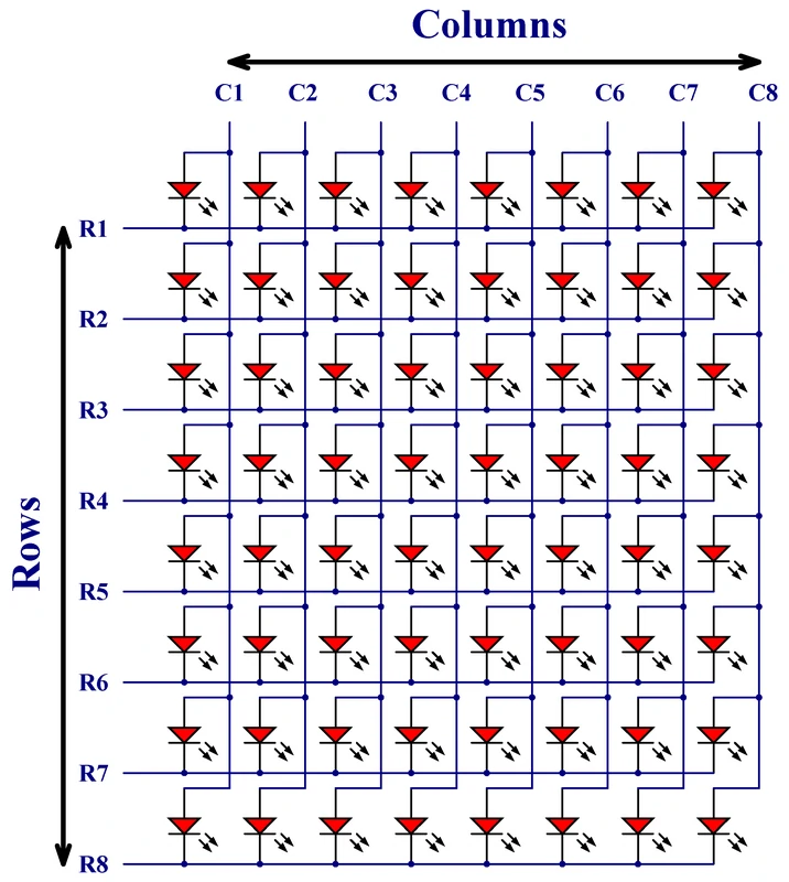
An LED dot matrix display consists of a grid of LEDs arranged in a rectangular matrix pattern. The internal connection of an LED dot matrix display can vary depending on the specific model and configuration, but in general, the matrix is arranged into rows and columns. The rows and columns are connected to driver circuits that control the LEDs in that row or column. The following image shows the internal connection of LEDs of a 8×8 dot matrix display with common cathode rows, common anode columns configuration (some displays has a common anode rows, common cathode columns configuration, LEDs are just reversed polarity):
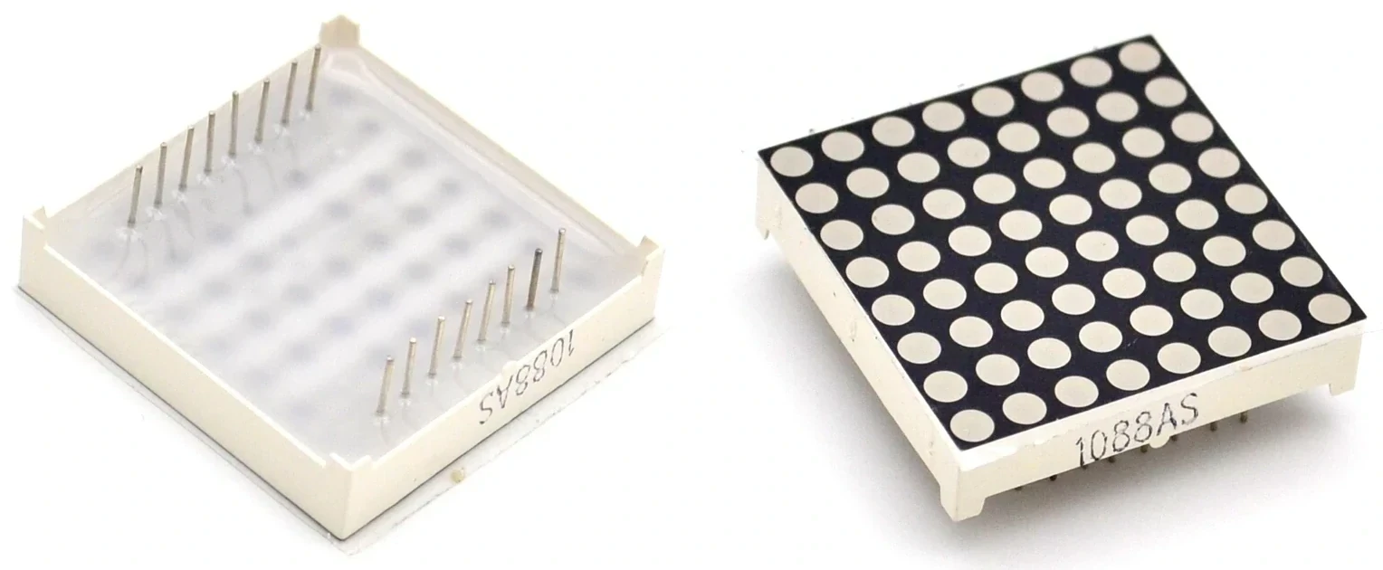
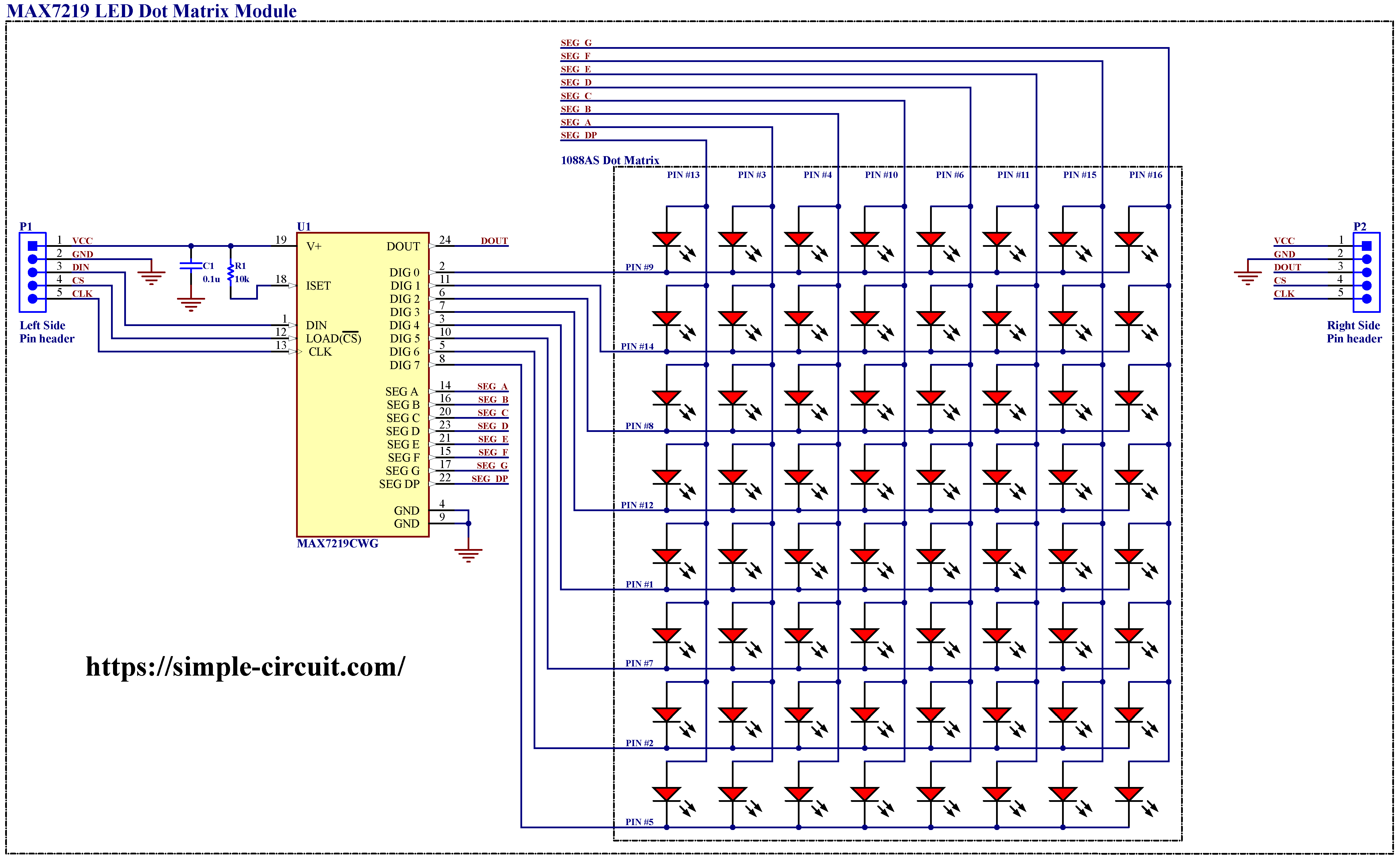
And the image below shows the 1088AS LED matrix type which also has a row cathode, column anode configuration:
Each LED in the matrix has two leads, an anode (+) and a cathode (-), which are connected to a column and row, respectively. A 8×8 dot matrix display has a total of 64 LEDs, since each LED has two leads then we should have a total of 128 pins which can be reduced to 65 if all LED anode or cathode leads are connected together. This number is still high and can be reduced to 16 by connecting display LEDs as shown above. So, with 16 pins we are able to control up to 64 LEDs.
To control the LED dot matrix display, the previous 16 pins (8 row pins and 8 column pins) are connected to a driver circuit that controls all the LEDs. To light up a specific LED in the matrix, the driver circuit for the corresponding column & row is activated to supply power between the anode & the cathode of that LED. This causes a current to flow through the LED, lighting it up.
To display text, symbols, or graphics on the matrix, the driver circuits must be activated in a specific sequence to turn on the appropriate LEDs. This is typically done using a microcontroller or other digital device that sends control signals to the driver circuits using a serial or parallel interface.
Similar to a multi-digit 7-segment display, the LED dot matrix display must also be refreshed at a rate that is fast enough to maintain the perception of a steady image. The process of refreshing the LED dot matrix display is also typically done using a technique called multiplexing.
The MAX7219 LED Dot Matrix Display Module:
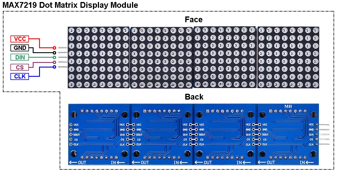
One of the most used dot matrix display module by hobbyists and DIY dot matrix projects is the MAX7219 module. It is a 8×8 LED dot matrix display module contains the MAX7219 integrated circuit (IC) from Maxim Integrated (subsidiary of Analog Devices) and all the necessary components.
The MAX7219 IC contains a serial interface that allows a microcontroller or other digital device to control the LED dot matrix display using a minimal number of control pins.
The image below shows a MAX7219 LED dot matrix module:
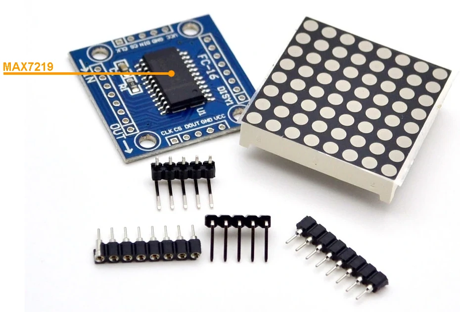
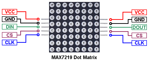
The MAX7219 module typically has 5 input pins and 5 output pins (left and right pin headers). Here’s a brief overview of the pinout:
- VCC: power supply voltage (typically 5V), connected to power supply positive terminal.
- GND: ground, connected to power supply ground or negative terminal.
- DIN: data input pin, used to send data to the module, connected to digital output pin of the microcontroller system.
- CS: chip select pin, used to enable or disable the module, also called as LOAD, connected to digital output pin of the microcontroller system.
- CLK: clock input pin, used to synchronize the data transfer, connected to digital output pin of the microcontroller system.
All output pins are connected to the next cascaded module including the DOUT pin which is connected to DIN pin of the next module.
The MAX7219 module circuit diagram is shown below. It is a simple circuit since it requires few components and can be implemented even in a breadboard circuit, it just requires a lot of wirings.
Note that resistor labeled as R1 (10k) which is connected between V+ and ISET pins of the MAX7219 IC, is used to control brightness of the dot matrix display, it is well knows as hardware brightness control (refer to MAX7219 datasheet to see brightness configuration as a function of R1 value).
The good thing with the MAX7219 IC is that it is designed to be easily cascaded to control larger LED dot matrix displays by connecting multiple MAX7219 ICs together in a daisy chain configuration, it is possible to control multiple displays or arrays using a single microcontroller or other digital device.
To cascade MAX7219 ICs, the data output of one IC is connected to the data input of the next IC in the chain. The clock and chip select pins of each IC are connected together in a common bus, allowing for easy communication between the ICs.
In a cascaded configuration, each MAX7219 IC is responsible for controlling a specific section of the display. The microcontroller or other digital device sends data and commands to the first IC in the chain, which then passes the data along to the next IC, and so on, until all of the connected ICs have received the data.
When multiple MAX7219 ICs are used in a cascaded configuration, it is important to ensure that the power supply can provide enough current to drive all of the connected LEDs. Additionally, the total number of LEDs being controlled must be taken into account, as the data transfer rate may need to be adjusted to ensure that the refresh rate is sufficient to maintain a stable display.
Simply, a four MAX7219 dot matrix display module when cascaded will be as shown below:
Interfacing MAX7219 LED Dot Matrix with Arduino:
This tutorial shows how to interface Arduino board with MAX7219 dot matrix display module and how to print texts and numbers on the this display. We’ll also see the simulation of this Arduino project using Proteus simulation software.
Hardware required:
This is a summary of project required parts.
- Arduino board
- MAX7219 LED dot matrix display module (4 cascaded devices) —> MAX7219 IC datasheet
- External 5V, 1A source
- Breadboard & some jumper wires
The given image below shows our example circuit diagram of the interfacing of Arduino uno board with MAX7219 dot matrix display where a four cascaded dot matrix modules are used (the same module shown above).
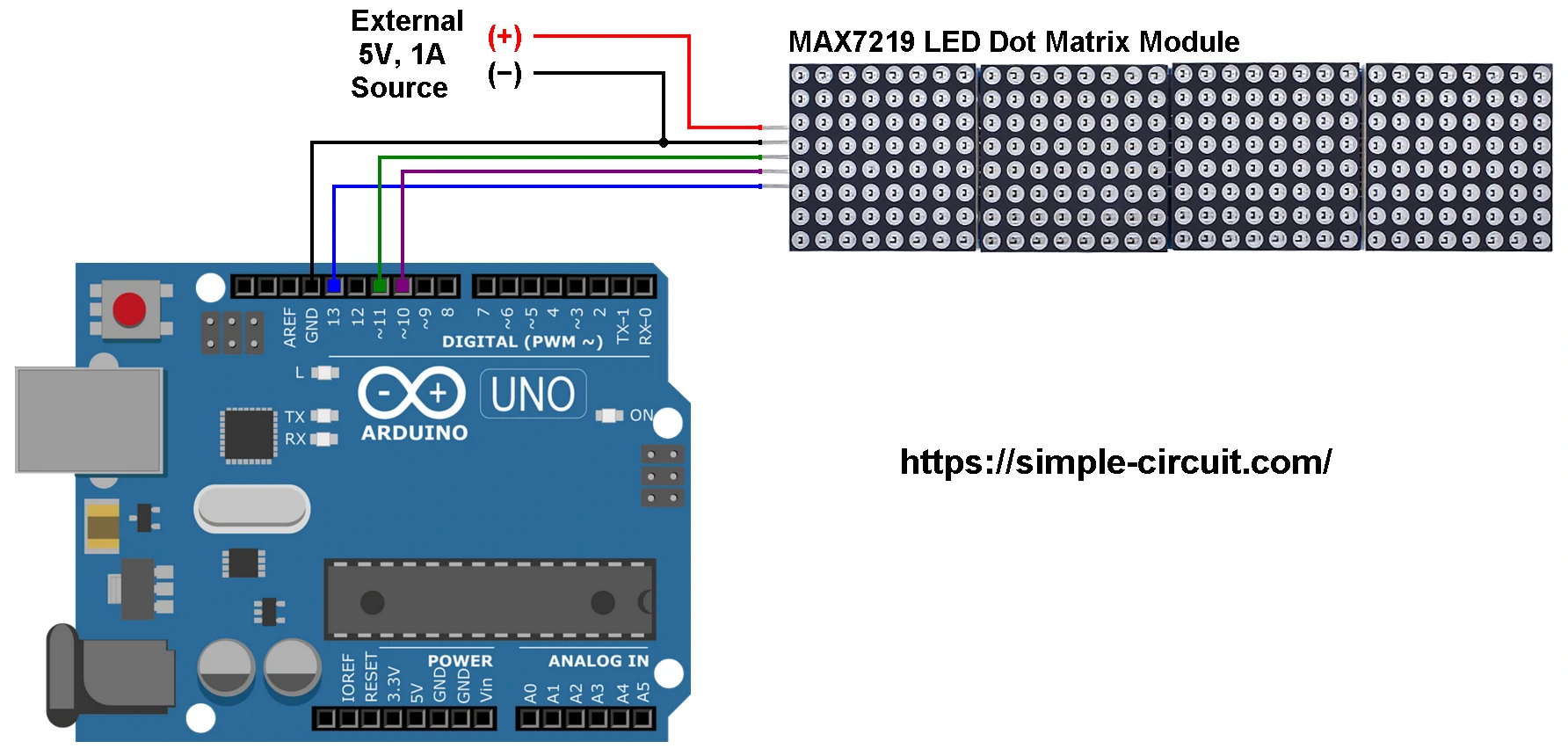
As shown in the circuit diagram, the wring is very simple as described below:
MAX7219 module GND pin is connected to Arduino GND pin.
MAX7219 module DIN pin is connected to Arduino digital pin 11.
MAX7219 module CS (LOAD) pin is connected to Arduino digital pin 10.
MAX7219 module CLK pin is connected to Arduino digital pin 13.
The MAX7219 module has a total of 256 LEDs and powering this number of LEDs requires a lot of current the Arduino board and most Laptop USB ports cannot provide. For this reason an external power source of 5V and at least 1A is needed. This power supply positive terminal is connected to VCC pin of the MAX7219 module and negative terminal (or ground) is connected to GND pin of the MAX7219 module.
Note that Arduino digital pins 10, 11, and 13 are hardware SPI pins of the ATMEGA328P microcontroller respectively for SS (Slave Select), MOSI (Master-Out Slave-In) and SCK (Serial Clock).
Interfacing MAX7219 LED Dot Matrix with Arduino Code:
To be able to compile project Arduino code, two libraries for the MAX7219 display are required. The first library is “MD_MAX72xx” which can be installed by going to:
Sketch menu —> Include Library —> Manage Libraries. In the Library Manager, search for “MD_MAX72xx” and install the library made by MajicDesigns.
The 2nd library is “MD_Parola” which also can be installed online using Arduino IDE Library Manager, just search for “MD_Parola” and install the library made by MajicDesigns.
GitHub links for the two libraries:
MD_MAX72XX
MD_Parola
The “MD_Parola” is a nice library for dot matrix display modules and it does support different hardware types. The given link below contains a useful documentation of this library:
Parola Library for Arduino Documentation
Programming hints:
All the used libraries are included in the Arduino code as given below:
1 2 3 | #include <MD_Parola.h> // include MajicDesigns Parola library #include <MD_MAX72xx.h> // include MajicDesigns MAX72xx LED matrix library #include <SPI.h> // include Arduino SPI library |
MD_Parola Library configuration:
As mentioned above, we have a four cascaded MAX7219 devices and this number is defined in the Arduino code as shown below.
The CS (LOAD) pin of the display module is connected to Arduino digital pin 10.
Note that we’re using dot matrix type: FC-16. It’s also defined in Arduino code.
1 2 3 4 | #define HARDWARE_TYPE MD_MAX72XX::FC16_HW // this line defines our dot matrix hardware type #define MAX_DEVICES 4 // define number of total cascaded modules #define CS_PIN 10 // define CS (Chip Select) pin MD_Parola display = MD_Parola(HARDWARE_TYPE, CS_PIN, MAX_DEVICES); |
Rest of code is described through comments.
Full Arduino Code:
1 2 3 4 5 6 7 8 9 10 11 12 13 14 15 16 17 18 19 20 21 22 23 24 25 26 27 28 29 30 31 32 33 34 35 36 37 38 39 40 41 42 43 44 45 46 47 48 49 50 51 52 53 54 | /************************************************************************************ * Interfacing MAX7219 LED dot matrix display with Arduino - Simple display example. * This is a free software with NO WARRANTY. * https://simple-circuit.com/ /************************************************************************************/ #include <MD_Parola.h> // include MajicDesigns Parola library #include <MD_MAX72xx.h> // include MajicDesigns MAX72xx LED matrix library #include <SPI.h> // include Arduino SPI library #define HARDWARE_TYPE MD_MAX72XX::FC16_HW // this line defines our dot matrix hardware type #define MAX_DEVICES 4 // define number of total cascaded modules #define CS_PIN 10 // define CS (Chip Select) pin MD_Parola display = MD_Parola(HARDWARE_TYPE, CS_PIN, MAX_DEVICES); // Arduino setup function void setup(void) { // initialize the dot matrix display display.begin(); // set the intensity (brightness) of the display (choose a number between 0 and 15) display.setIntensity(3); // clear the whole display display.displayClear(); // print some texts on the display display.print("Hello!"); delay(5000); display.print("Arduino"); delay(2000); display.print("led dot"); delay(2000); display.print("matrix"); delay(2000); display.print("example"); delay(5000); } uint16_t i = 0; // Arduino main loop function void loop(void) { // print a number on the display display.print(i); i++; // increment 'i' delay(1000); // wait a second } // end of code. |
Interfacing MAX7219 LED Dot Matrix with Arduino Video:
The following video shows my simple DIY circuit of this project where Arduino NANO board is used.
Interfacing MAX7219 LED Dot Matrix with Arduino Proteus Simulation Video:
This project can be easily simulated using Proteus simulation software as shown in this video.
Arduino with MAX7219 module Proteus simulation file download:
Proteus simulation file of this project can be downloaded from the below Google Drive link. Use Proteus version 8.15 or higher to open it.
DOWNLOAD
Discover more from Simple Circuit
Subscribe to get the latest posts sent to your email.


Great post! I loved the detailed explanation on interfacing the MAX7219 with Arduino. The step-by-step instructions made it easy to follow along. I can’t wait to try out the code and see the display in action!
well presented and informative.
Good job
Great tutorial! I love how you broke down the steps for interfacing the MAX7219 with Arduino. The example code was easy to follow, and I can’t wait to try it out on my own project. Thanks for sharing!
excellent information sir/ma’am,
thank you for the inputs,
helped me a lot.