One of the simplest microcontroller projects is the interfacing with 1602 LCD screen, it of course can help showing data stored inside the microcontroller such as texts & numbers and also may be used for some debugging purposes. The LCD simply acts like a Human-Machine Interface device (HMI).
This post shows how to interface STMicroelectronics MCU STM32F103C8T6 Blue Pill development board with 1602 LCD where Arduino IDE is used to write the interfacing program. We will also see the simulation of the STM32F103C8T6 Blue Pill board with 16×2 LCD using Proteus simulation software.
The 16×2 LCD is a very popular and simple display device, it contains a the HITACHI HD44780U Dot Matrix Liquid Crystal Display Controller/Driver (or compliant controller). Interfacing this display with a microcontroller requires at least 6 data pins. The number 1602 or 16×2 means the display module has 16 columns and 2 rows, this means a total of 32 character can be displayed at once.
Interfacing STM32F103C8T6 Blue Pill board with 16×2 LCD circuit:
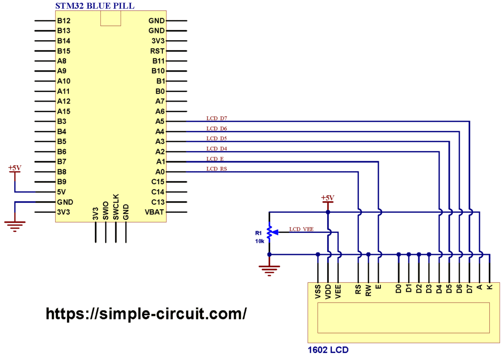
Project circuit diagram is shown below.
Hardware required:
This is a summary of circuit required parts (circuit schematic diagram may contain some component parameters not mentioned below).
- STM32 Blue Pill board —> STM32F103C8T6 32-bit Arm Cortex-M3 MCU
- 1602 LCD screen —> HD44780 datasheet
- 10k ohm variable resistor (R1)
- Breadboard & jumper wires…
- FTDI FT232RL USB-to-UART converter (for burning program file to the MCU)
Circuit description:
Our 16×2 LCD example circuit is extremely simple as few components and connections are required between the STM32F103C8T6 Blue Pill board and the display module.
The main power source of the circuit comes from the micro USB port of the STM32 Blue Pill board with voltage of 5V. The board contains a voltage regulator that feeds the STM32F103C8T6 microcontroller with 3.3V. The 16×2 LCD module is powered with 5V from the STM32 Blue Pill board where its ‘VDD’ pin is connected to ‘5V’ pin of the board.
Other 1602 LCD pins are connected to the STM32 Blue Pill board as follows:
RS —> pin PA0
E —> pin PA1
D4 —> pin PA2
D5 —> pin PA3
D6 —> pin PA4
D7 —> pin PA5
VSS, RW, D0, D1, D2, D3 and K are connected to circuit ground
VEE to the variable resistor (or potentiometer) output
VDD and A to +5V (from the board).
VEE pin is used to control the contrast of the LCD. A (anode) and K (cathode) are the back light LED pins.
Interfacing STM32F103C8T6 Blue Pill board with 16×2 LCD Arduino code:
Arduino IDE is used to write project code, the STM32 Blue Pill board has to be added to the IDE before compilation.
The STM32 Blue Pill board can be installed using Arduino IDE Boards Manager.
The FT232RL USB to serial UART converter is used to program the STM32F103C8T6 microcontroller, the ST-LINK V2 programmer also can be used and it is supported by the Arduino IDE.
The STM32 Blue Pill board package comes with a nice LCD library that supports different LCD connections including the 4-bit and 8-bit operating modes and the ‘RW’ pin connection.
In this example 4-bit mode with ‘RW’ pin connected to ground is used.
The LCD library is included in the Arduino code as shown below:
1 2 | // include LCD library code #include <LiquidCrystal.h> |
The connections between the STM32 Blue Pill board and the 16×2 LCD is as shown in the above circuit schematic, it is defined in the Arduino code as shown below:
1 2 | // LCD module connections (RS, E, D4, D5, D6, D7) LiquidCrystal lcd(PA0, PA1, PA2, PA3, PA4, PA5); |
Rest of code is described through comments.
1 2 3 4 5 6 7 8 9 10 11 12 13 14 15 16 17 18 19 20 21 22 23 24 25 26 27 28 29 30 31 32 33 34 35 36 37 38 39 40 41 42 | /************************************************************************ * * Interfacing STM32F103C8T6 Blue Pill board with 16x2 LCD screen. * This is a free software with NO WARRANTY - Use it at your own risk! * http://simple-circuit.com/ * ************************************************************************/ // include LCD library code #include <LiquidCrystal.h> // LCD module connections (RS, E, D4, D5, D6, D7) LiquidCrystal lcd(PA0, PA1, PA2, PA3, PA4, PA5); void setup() { // initialize the LCD screen with 16 column & 2 rows // in case of 20x4 LCD use: lcd.begin(20, 4); lcd.begin(16, 2); lcd.setCursor(0, 0); // move cursor to position (0, 0) -- 1st column & 1st row lcd.print("STM32 BLUE PILL"); // print text on the LCD lcd.setCursor(0, 1); // move cursor to position (0, 1) -- 1st column & 2nd row lcd.print("LCD Example"); // print text on the LCD delay(5000); // wait 5 seconds lcd.clear(); // clear the display lcd.setCursor(0, 0); // move cursor to position (0, 0) -- 1st column & 1st row lcd.print("Hello world!"); // print text on the LCD } void loop() { lcd.setCursor(0, 1); // move cursor to position (0, 1) -- 1st column & 2nd row uint32_t n = millis() / 1000; // use millis() function to get number of seconds since power up lcd.print( n ); // print the variable 'n' on the LCD delay(1000); // wait a second } // end of code. |
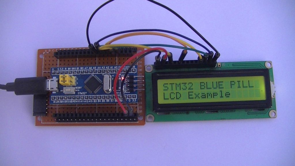
The following video shows my simple DIY circuit:
Proteus Simulation:
The interfacing of ST32F103C8T6 Blue Pill with 1602 LCD project can be simulated using Proteus simulation software as shown in the video below:
Proteus simulation file download:
Interfacing STM32F103C8T6 Blue Pill with 16×2 LCD Proteus simulation file download link is below, use Proteus version 8.15 or higher in order to be able to open it.
Download
And the link below is Proteus library for the STM32F103C8T6 Blue Pill board. After the download put the file in Proteus library folder, for example in my case Proteus library folder path is: C:\ProgramData\Labcenter Electronics\Proteus 8 Professional\Library
Proteus library for the STM32F103C8T6 Blue Pill board
Discover more from Simple Circuit
Subscribe to get the latest posts sent to your email.
Hi!
Could You explain in details, how You installed the STM32 Blue Pill board using Arduino IDE Boards Manager?
Thanks!