This post shows how to build a simple DIY single phase power meter station mainly based on Microchip PIC18F46K22 8-bit microcontroller.
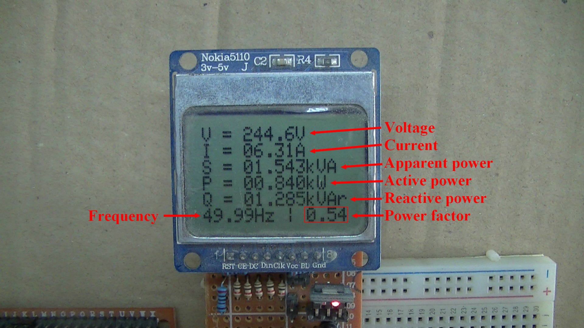
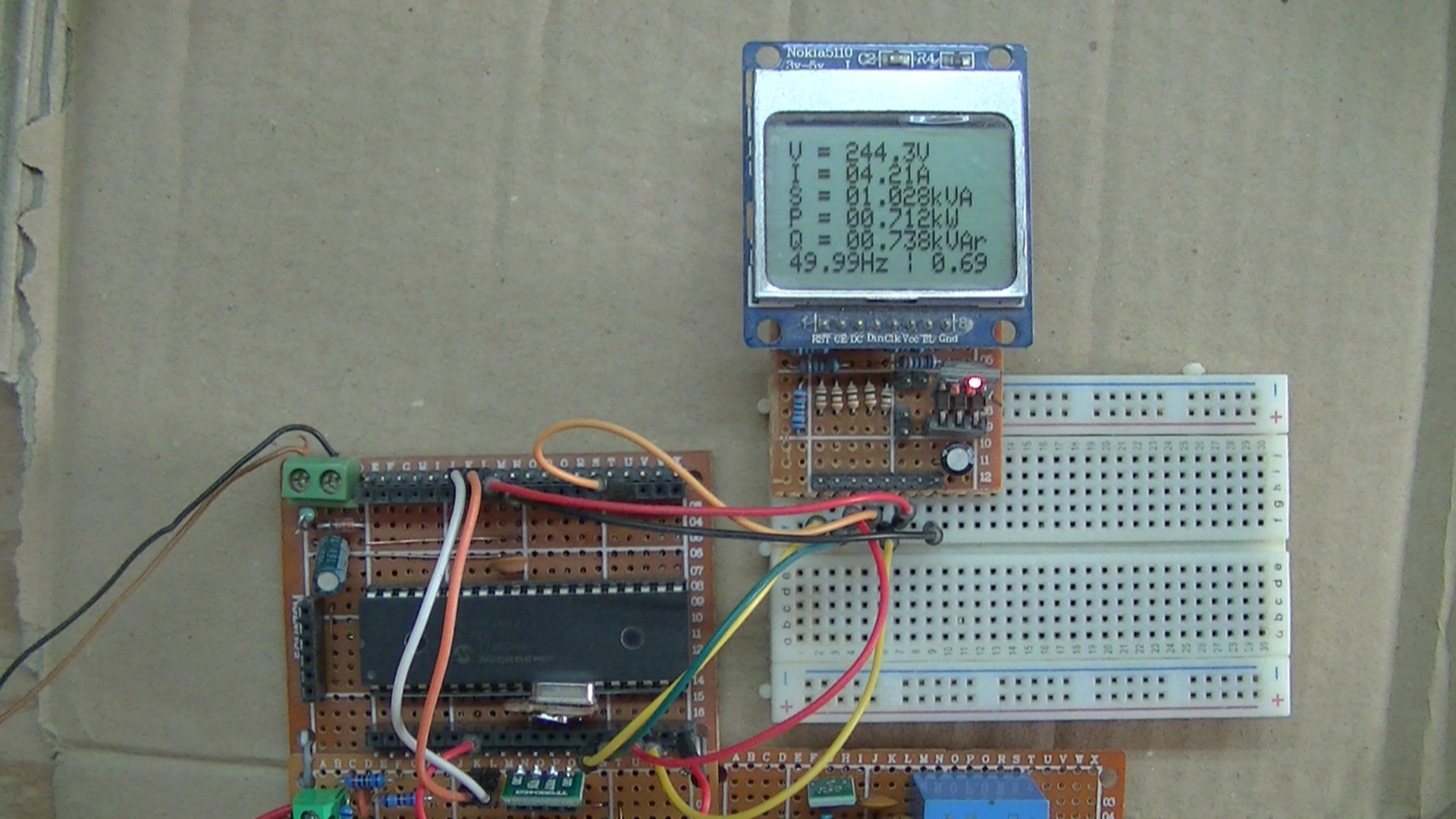
Power quantities which are: Voltage, Current, Apparent Power, Active Power, Reactive Power, Frequency and Power Factor are printed on Nokia 5110 LCD screen as shown in the below images.
Theoretically, this DIY power station can measure electric currents up to 50 Amps and voltages up to 500V, this means it should work with home electric network (2-phase and 1-phase AC loads).
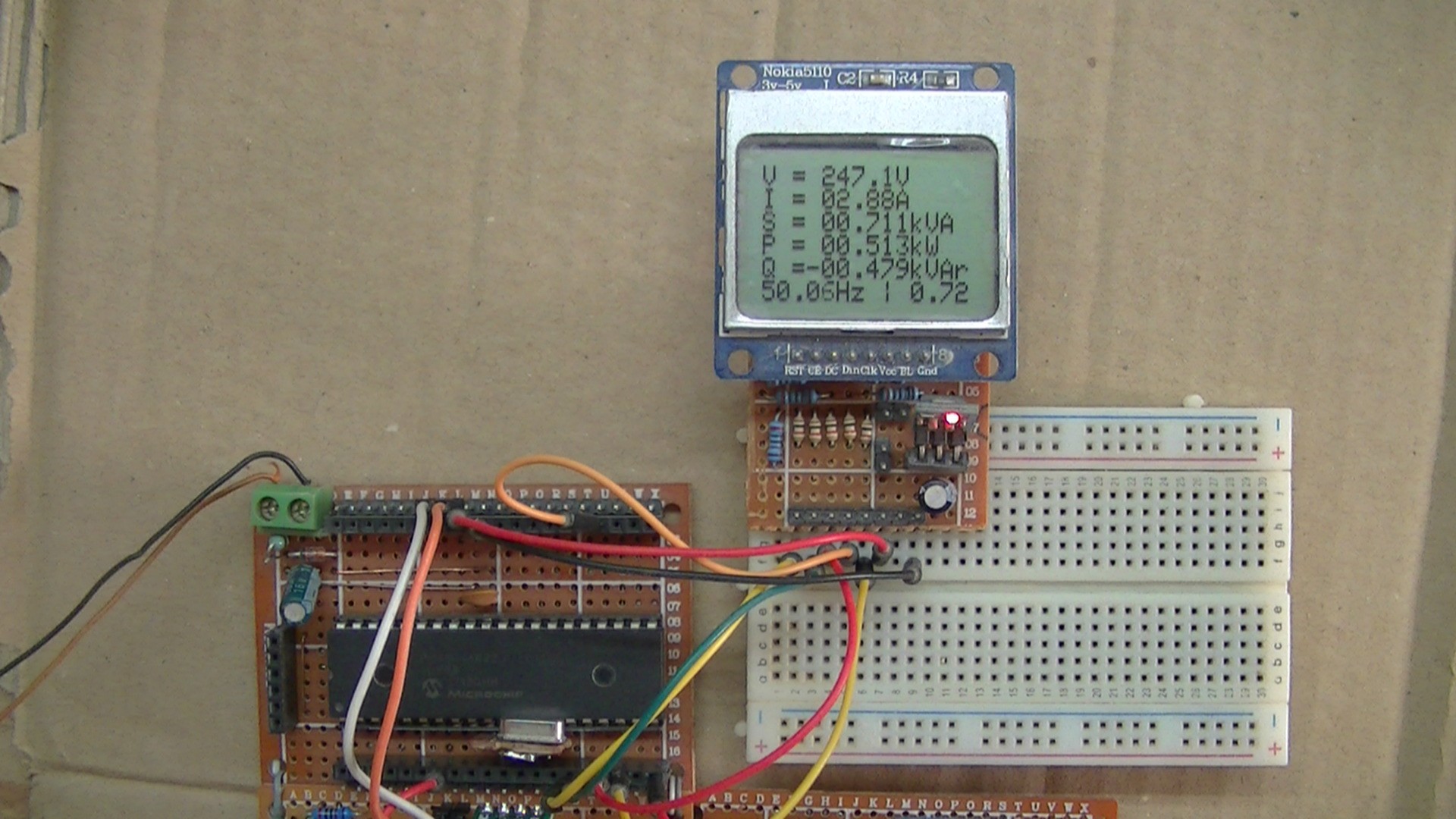
This circuit can measure positive and negative values of Active Power, Reactive Power and power Factor. A negative Active Power means that the power is transferred from the load to the source (reverse power), this occurs only when we have a real power source such as generator. A negative Reactive Power means that the power is transferred from the load to the source, this occurs when we have reactive power source such as capacitor.
CCS C Compiler is used in this project.
Hints:
No warranty is provided with this project, so do it at your own risk!
A part of project circuit may be subjected to a high voltage level which is very harmful to human body, so be-careful!
Abbreviations:
AC: Alternating Current
DC: Direct Current
TRMS: True Root Mean Square.
ADC: Analog-to-Digital Converter
CT: Current Transformer
VT: Voltage Transformer
PCB: Printed Circuit Board
DIY: Do It Yourself
Single phase power meter station with PIC18F46K22 MCU circuit:
Project circuit diagram is shown below (click on the image for full resolution view).
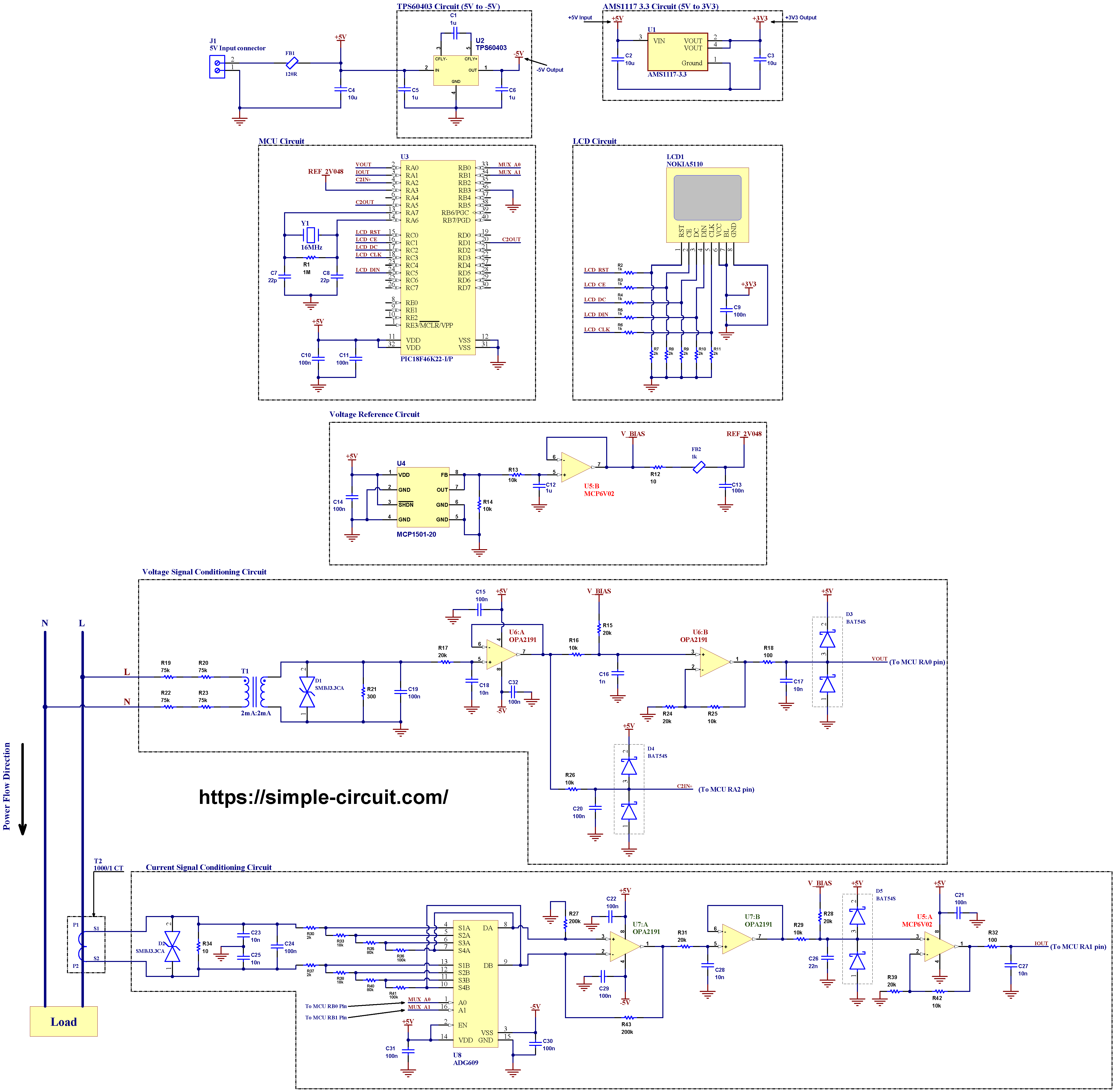
The main power source voltage of the circuit is 5V, it’s connected to J1 connector (5V Input connector) where pin 1 is negative (GND) and pin 2 is positive terminal.
Hardware required:
This is a summary of circuit required parts (circuit schematic diagram may contain some component parameters not mentioned below).
- PIC18F46K22 microcontroller (U3) —> datasheet
- Nokia 5110 LCD screen
- Current-type voltage transformer 2mA/2mA (T1)
- Current transformer with turns ratio 1000:1 (T2)
- ADG609 analog multiplexer (U8) —> details
- 2 x OPA2191 op amp (U6, U7) —> details
- MCP6V02 op amp (U5) —> details
- MCP1501-20 2.048V voltage reference (U4) —> details
- TPS60403 charge pump voltage inverter (U2) —> details
- AMS1117-3.3 voltage regulator
- 3 x BAT54S dual serial small signal Schottky diode
- 2 x SMBJ3.3CA TVS diode
- 16MHz quartz crystal (Y1)
- 3 x 10uF capacitor (C2, C3, C4)
- 4 x 1uF capacitor (C1, C5, C6, C12)
- 15 x 100nF capacitor (C9, C10, C11, C13, C14, C15, C19, C20, C21, C22, C24, C29, C30, C31, C32)
- 22nF capacitor (C26)
- 6 x 10nF capacitor (C17, C18, C23, C25, C27, C28)
- 1nF capacitor (C16)
- 2 x 22pF capacitor (C7, C8)
- 1M Ohm resistor (R1)
- 2 x 200k Ohm resistor (R27, R43)
- 2 x 100k Ohm resistor (R36, R41)
- 2 x 80k Ohm resistor (R35, R40)
- 4 x 75k Ohm resistor (R19, R20, R22, R23)
- 6 x 20k Ohm resistor (R15, R17, R24, R28, R31, R39)
- 2 x 18k Ohm resistor (R33, R38)
- 7 x 10k Ohm resistor (R13, R14, R16, R25, R26, R29, R42)
- 7 x 2k Ohm resistor (R7, R8, R9, R10, R11, R30, R37)
- 5 x 1k Ohm resistor (R2, R3, R4, R5, R6)
- 300 Ohm resistor (R21)
- 2 x 100 Ohm resistor (R18, R32)
- 2 x 10 Ohm resistor (R12, R34)
- 1k Ohm ferrite bead (FB2)
- 120 Ohm ferrite bead (FB1)
- 5V source
- Breadboard & jumper wires…
- PIC MCU programmer (PICkit 3, PICkit 4 …)
Note for better accuracy that the following resistors should have a tolerance no more than 1%:
- R19, R20, R22, R23 (75k) –> 0.25W Through hole resistors are recommended in order to handle voltage rating of 500V.
- R21 (300R)
- R16, R25, R29, R42 (10k)
- R15, R24, R28, R39 (20k)
- R27, R43 (200k)
- R30, R37(2k)
- R33, R38 (18k)
- R35, R40 (80k)
- R36, R41 (100k)
- R34 (10R)
Circuit description:
The PIC18F46K22 microcontroller used in this project is a 40-pin 8-bit MCU supplied with 5V at VDD pins (#11 and #32). A Quartz crystal with frequency of 16MHz is used as an external clock source to the MCU, with the PLL enabled in the software the MCU becomes running at frequency of 16 x 4 = 64MHz.
As mentioned earlier, all power quantities are displayed on Nokia 5110 LCD screen. This display contains the PCD8544 controller, it is similar to the one used in Nokia 5110 mobile phone, it uses SPI interface protocol with maximum clock frequency of 4 MHz and requires 5 control pins.
The resolution of this LCD is 84 x 48 which means it has 4032 pixels. This module works with 3.3V only and it doesn’t support 5V (not 5V tolerant), this means interfacing it with 5V microcontroller such as the PIC18F46K22 MCU requires voltage level shifter.
To get a 3.3V supply I used the AMS1117 3.3 LDO regulator, it just gives a regulated 3.3V from the 5V input.
To connect the PIC18F46K22 data lines to the LCD module, I used voltage divider for each line. This means there are 5 voltage dividers, each one consists of 1k and 2k resistors, this drops control voltage from 5V into 3.3V.
Actually, choosing the values of voltage divider resistors depends on many factors such as: maximum frequency and input pin capacitance but 1k & 2k will do the job as it should be in our case, however, using a 3.3V microcontroller is recommended when dealing with 3.3V devices.
So, the Nokia 5110 LCD pins are connected to PIC18F46K22 MCU as follows (each one through voltage divider):
RST (reset) pin is connected to pin RC0 (#15),
CE (chip enable) pin is connected to pin RC1 (#16),
DC (data/command) pin is connected to pin RC2 (#17),
CLK (clock) pin is connected to pin RC3 (#18),
DIN (data in) pin is connected to pin RC5 (#24).
VCC and BL are connected to AMS1117-3V3 regulator output pin and GND is connected to circuit ground (0V).
ADC Voltage reference:
I used the MCP1501-20 high-precision buffered voltage reference from Microchip to get a precise voltage of 2.048V which is then used as a positive voltage reference for the PIC18F46K22 microcontroller ADC module and a bias voltage for voltage and current AC signals.
I also used 1 op amp of U5 (MCP6V02) as voltage follower to buffer the output voltage of the MCP1501-20.
Voltage signal conditioning circuit:
As we can not connect mains wires directly to the microcontroller due to the high voltage level, I used a small current-type voltage transformer labeled in the circuit schematic as T1. The full name of the one I’m using in this project is DL-PT202D with turns ratio of 1. The input of this transformer is current and the output is also current proportional to the input. I used 4 current limiting resistors (R19, R20, R22, R23) each of 75k to keep transformer input current under its rated one (2mA RMS) when it is subjected to 500V AC.
In order to handle 500V with no problem and for nice accuracy, the last 4 resistors should be a through hole type, 1/4W with tolerance of 0.1%.
With this transformer the high voltage circuit is galvanically isolated from low voltage circuit.
There are many alternatives to the voltage transformer that I’m using such as ZMPT112, any other replacement should have the same voltage rating (or higher) and ratio (2mA/2mA).
This type of transformers gives a significant safety factor to the circuit as it provide a galvanic isolation between the high voltage mains circuit and the low voltage control circuit which is in a direct contact with human body and other electronic equipments. They also have a small size, low cost and require few components.
A resistor of 300 Ohm (R21) is connected across the secondary of the voltage transformer, a voltage drop will be created across this resistor when an electric current passes through it.
With the created voltage, the MCU will be able to get voltage samples and also measure line frequency.
Current signal conditioning circuit:
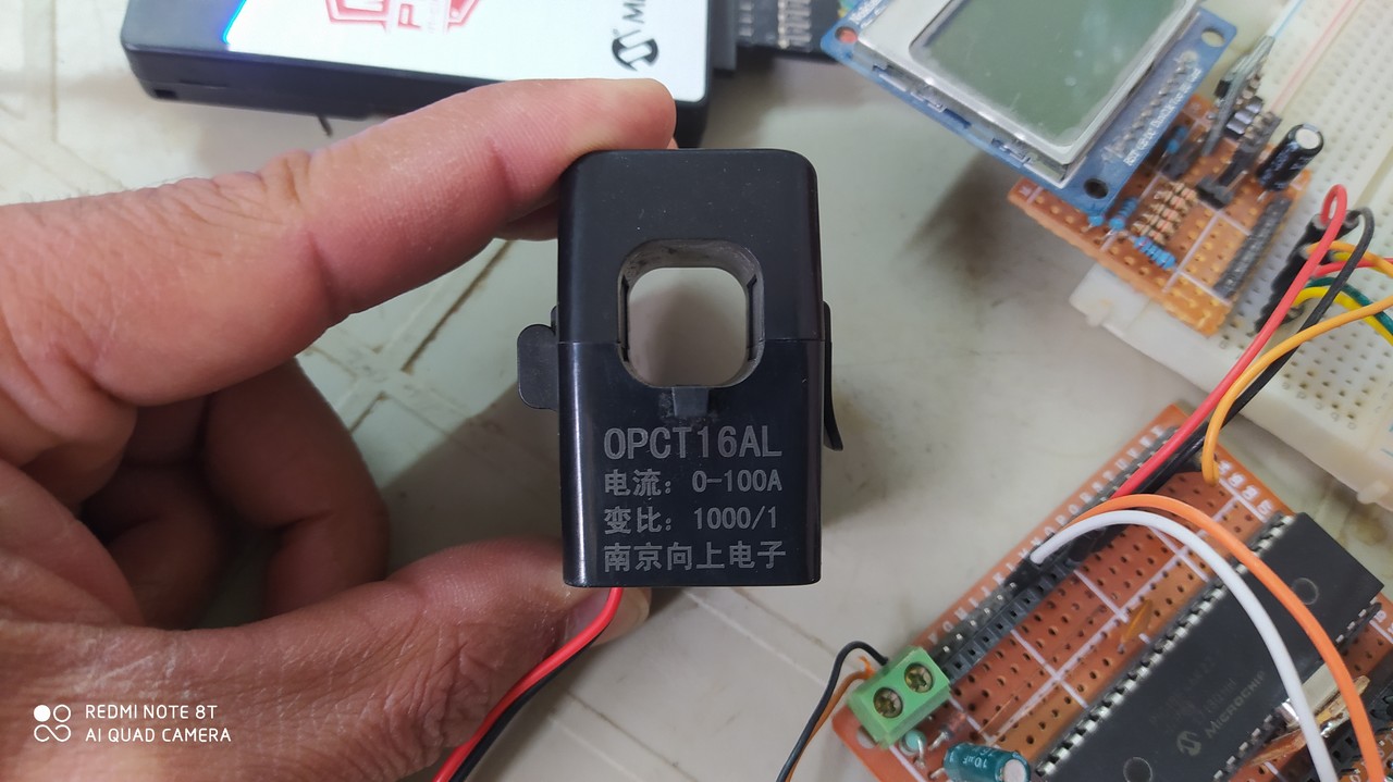
As shown in project circuit schematic diagram above, the current transformer which noted as T2 has turns ratio of 1000/1, the secondary of the current transformer is connected to a shunt resistor with resistance of 10 Ohm (R34), this means at a load current of 50A AC the voltage generated across R34 will be: 50 x 10 / 1000 = 500 mV AC.
I used the ADG609 analog multiplexer from Analog Devices and OPA2191 op amp (U7) from Texas Instruments with some resistors to build a programmable gain amplifier with gains: 1, 2, 10 & 100 where we can change the gain through the ADG609 inputs A0 (pin #1) and A1 (pin #16). For example if A0 = A1 = LOW then the gain = 100, and so on.
The ADG609 analog multiplexer and the two OPA2191 op amp ICs (U6, U7) are powered with bipolar supply of voltage ±5V, I used the TPS60403 60mA charge pump voltage inverter from Texas Instruments to get -5V where it automatically generates a -5 V from the +5 V supply.
Another alternatives with pin compatible to the ADG609 are: ADG409 –datasheet– and ADG5409 –datasheet-, the best one is the ADG5409 since its typical ON resistance is low (13.5 Ohm), but according to device’s datasheet the ADG409 as well as the ADG5409 require dual supply with minimum voltage of ±9.
Resistor R35 & R40 have a resistance of a not well used value -80k Ohm-, we may connect two resistors in parallel to get 80k, for example in my DIY circuit I used 120k in parallel with 240k.
Note that for better accuracy all the PGA circuit resistors should have a tolerance of 0.1%. A tolerance of 1% can also be used but it will directly affects the accuracy of the measurements.
Single phase power meter with PIC18F46K22 MCU C code:
The C code below is for CCS C compiler, it was tested with version 5.112.
To be able to compile the C code with no error, a driver C file for Nokia 5110 LCD is required, download link is the one below. After the download just put the file in project folder:
NOKIA_LCD.c
Project microcontroller C code calculates average and RMS values of AC signals, the average value is just used in the RMS calculations. The MCU only shows the RMS values of mains voltage and load current on the LCD.
Simply the average (mean or DC offset) value in discrete-time is the sum of all sample values divided by number of samples:
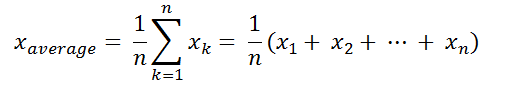
and the RMS value in discrete-time domain can be calculated using the following equation:

The PIC18F46K22 microcontroller contains a 10-bit ADC module, with a positive voltage reference of 2.048 V, a 0 V is digitally represented by 0 and a 2.048 V is represented by 1023.
Programming hints:
As we have a 10-bit ADC module working in the range [0, 2.048V], the MCU makes 64 samples every 1 cycle for both Voltage and Current.
For a 50 Hz signal the period is 20 ms, the MCU takes one sample every 20000/64 = 312.5 us. I used CCP5 (Capture, Compare, PWM) module to start an ADC conversion every 312.5 us where the module is configured to use Timer5 for the compare operation, once the conversion is complete ADC interrupt saves the digital values on its corresponding array. The array element is incremented every new reading until the filling of all elements and completion of the cycle.
To measure voltage frequency I used PIC18F46K22 MCU internal analog comparator for zero crossing event detection and CCP4 with Timer3 for measuring the pulse widths and therefor line frequency. After every cycle CCP5 registers updated in order to adapt the new cycle period, number of samples which is 64 and ADC sampling frequency.
At all times the microcontroller automatically changes the gain of the PGA circuit according to the load current, if the load current is less than 0.5A the MCU sets the gain to 100, if the load current is between 0.5A & 5A then the MCU sets the gain to 10, if the current is between 5A & 25A then the MCU sets the gain to 10 and if the load current is higher than 25A the MCU sets the gain to 1.
Full CCS C code:
1 2 3 4 5 6 7 8 9 10 11 12 13 14 15 16 17 18 19 20 21 22 23 24 25 26 27 28 29 30 31 32 33 34 35 36 37 38 39 40 41 42 43 44 45 46 47 48 49 50 51 52 53 54 55 56 57 58 59 60 61 62 63 64 65 66 67 68 69 70 71 72 73 74 75 76 77 78 79 80 81 82 83 84 85 86 87 88 89 90 91 92 93 94 95 96 97 98 99 100 101 102 103 104 105 106 107 108 109 110 111 112 113 114 115 116 117 118 119 120 121 122 123 124 125 126 127 128 129 130 131 132 133 134 135 136 137 138 139 140 141 142 143 144 145 146 147 148 149 150 151 152 153 154 155 156 157 158 159 160 161 162 163 164 165 166 167 168 169 170 171 172 173 174 175 176 177 178 179 180 181 182 183 184 185 186 187 188 189 190 191 192 193 194 195 196 197 198 199 200 201 202 203 204 205 206 207 208 209 210 211 212 213 214 215 216 217 218 219 220 221 222 223 224 225 226 227 228 229 230 231 232 233 234 235 236 237 238 239 240 241 242 243 244 245 246 247 248 249 250 251 252 253 254 255 256 257 258 259 260 261 262 263 264 265 266 267 268 269 270 271 272 273 274 275 276 277 278 279 280 281 282 283 284 285 286 287 288 289 290 291 292 293 294 295 296 297 298 299 300 301 302 303 304 305 306 307 308 309 310 311 312 313 314 315 316 317 318 319 320 321 322 323 324 325 326 327 328 329 330 331 332 333 334 335 336 337 338 339 340 341 342 343 344 345 346 347 348 349 350 351 352 353 354 355 356 357 | /********************************************************************** Single Phase power monitor station using PIC18F46K22 microcontroller. Power quantities are displayed on Nokia 5110 LCD screen. C Code for CCS C compiler. This is a free software with NO WARRANTY - Use it at your own risk!. http://simple-circuit.com/ /**********************************************************************/ // define Nokia LCD module pin connections #define LCD_RST PIN_C0 // reset pin, optional! #define LCD_CS PIN_C1 // chip select pin #define LCD_DC PIN_C2 // data/command pin // define programmable gain amplifier circuit control pins #define PGA1 PIN_B0 #define PGA2 PIN_B1 // define CT burden resistor in Ohm (resistor connected across CT secondary) #define CT_Burden 10 // define Voltage & Current correction factors (used as calibration factors) #define Voltage_Correction 1.016 #define Current_Correction 1 #include <18F46K22.h> #device ADC = 10 #fuses NOMCLR,NOLVP,NOBROWNOUT,PUT,NOXINST #use fast_io(B) #use fast_io(C) #use delay(XTAL = 16MHZ, CLOCK = 64MHZ) #include <stdint.h> #include <math.h> #use SPI(SPI1, MODE = 0, BITS = 8, STREAM = LCD, FORCE_HW, BAUD=4000000) #include <NOKIA_LCD.c> // CCP5 registers (CCP5 used to trigger ADC module) #byte CCPTMRS1 = getenv("SFR:CCPTMRS1") #byte CCP5CON = getenv("SFR:CCP5CON") #byte CCPR5L = getenv("SFR:CCPR5L") #byte CCPR5H = getenv("SFR:CCPR5H") // CCP4 registers (CCP4 used to measure Voltage frequency) #byte CCP4CON = getenv("SFR:CCP4CON") #byte CCPR4L = getenv("SFR:CCPR4L") #byte CCPR4H = getenv("SFR:CCPR4H") const uint8_t gain_table[4] = {100, 10, 2, 1}; // programmable gain amplifier gain values const uint8_t n = 64; // number of samples uint8_t m = 0, // sample number ( 0 <= m < n) m1 = 0, // used to specify the writing array (sample collecting and saving array) m2 = 0, // used to specify the reading array dis = 0, // variable for data display on LCD gain; // variable for PGA s gain selection struct PWR { int16_t Samples[2*n]; uint16_t RMS, SamplesSum, Average; }; struct PWR Voltage, Current; int1 s_pwr = 0; // a varibale to distinguish between Current & Voltage while // performing ADC readings (used only in ADC ISR) uint16_t ApparentPwr; int16_t ActivePwr, ReactivePwr; int8_t PwrFactor; uint16_t period = 0, freq = 0, CCP5; int1 ZC_Event = 0; // if = 1 --> ZC event occured // ADC ISR #INT_AD void ADC_ISR(void) { if (m < n) { if(s_pwr) { Voltage.Samples[m1 + m] = read_adc(ADC_READ_ONLY); set_adc_channel(1); // select AN1 channel (current sensing) Voltage.SamplesSum += Voltage.Samples[m1 + m]; s_pwr = 0; m++; // increment m for the next sample } else { Current.Samples[m1 + m] = read_adc(ADC_READ_ONLY) ; set_adc_channel(0); // select AN0 channel (voltage sensing) Current.SamplesSum += Current.Samples[m1 + m]; read_adc(ADC_START_ONLY) ; s_pwr = 1; } } } #INT_CCP4 void CCP4_ISR(void) { set_timer3(0); period = (uint16_t)CCPR4H << 8 | CCPR4L; ZC_Event = TRUE; } #INT_TIMER3 void TIMER3_ISR(void) { period = 40000; // set line frequency to 50Hz (default frequency) --> Period = 40000/2 = 20ms ZC_Event = TRUE; } // gain set function void gain_set(uint8_t g) { switch(g) { case 0: output_low(PGA1); output_low(PGA2); break; case 1: output_high(PGA1); output_low(PGA2); break; case 2: output_low(PGA1); output_high(PGA2); break; case 3: output_high(PGA1); output_high(PGA2); } } // main function void main(void) { delay_ms(100); setup_adc(ADC_CLOCK_DIV_64 | ADC_TAD_MUL_2); // set ADC module clock source to FOSC/64 = 1MHz // configure AN0 & AN1 pins as analog inputs & set voltage references to: VSS - VREF (external voltage reference) setup_adc_ports(sAN0 | sAN1, VSS_VREF); set_adc_channel(1); // select AN1 channel // analog comparator 2 configuration (used for ZC event detection) setup_comparator(CP2_B3_A2 | CP2_OUT_ON_A5); // PGA pins output_drive(PGA1); output_drive(PGA2); // SPI pins output_drive(PIN_C3); // SCK pin output_drive(PIN_C5); // MOSI pin // initialize the LCD LCD_Init(); // init done // you can change the contrast around (0 ... 63) to // adapt the display for the best viewing! LCD_SetContrast(50); // clear the whole LCD LCD_Clear(); LCD_GotoXY(0, 0); LCD_PrintC("V = 000.0V"); LCD_GotoXY(0, 1); LCD_PrintC("I = 00.00A"); LCD_GotoXY(0, 2); LCD_PrintC("S = 00.000kVA"); LCD_GotoXY(0, 3); LCD_PrintC("P = 00.000kW"); LCD_GotoXY(0, 4); LCD_PrintC("Q = 00.000kVAr"); LCD_GotoXY(0, 5); LCD_PrintC("00.00Hz | 0.00"); enable_interrupts(GLOBAL); // enable global interrupts // CCP5 configuration: -compare mode, Special Event Trigger // -Timer is reset & ADON is set CCP5CON = 0x0B; CCPTMRS1 = 0x09; // CCP5 – Capture/Compare modes use Timer5, PWM modes use Timer6 // CCP4 – Capture/Compare modes use Timer3, PWM modes use Timer4 // initial configuration of signal period (assume 50Hz frequency) period = 40000; CCP5 = period / 8; CCPR5H = CCP5 >> 8; // set compare value, 5000 (0x1388) ==> 312.5 us @ FOSC/4 clk input CCPR5L = CCP5; // CCP4 configuration CCP4CON = 0x05; // Capture mode: every rising edge // empty sample arrays for (uint8_t i = 0; i < 2*n; i++) { Voltage.Samples[i] = 0; Current.Samples[i] = 0; } Voltage.SamplesSum = 0; Current.SamplesSum = 0; // set up Timer5 (used by CCP5) set_timer5(0); setup_timer_5(T5_INTERNAL); // Timer 5 clock source, FOSC/4 ==> 16MHz clear_interrupt(INT_AD); // clear ADC interrupt flag bit enable_interrupts(INT_AD); // enable ADC interrupt clear_interrupt(INT_CCP4); // clear CCP4 interrupt flag bit enable_interrupts(INT_CCP4); // enable CCP4 interrupt // set up Timer3 (used by CCP4) set_timer3(0); setup_timer_3(T3_INTERNAL | T3_DIV_BY_8); clear_interrupt(INT_TIMER3); // clear Timer3 interrupt flag bit enable_interrupts(INT_TIMER3); // enable Timer3 interrupt // gain initial configuration gain = 0; gain_set(gain); while (TRUE) { uint32_t ch_voltage = 0; // variable for MCU analog input channel applied // RMS voltage while (m < n) ; // wait for 1 cycle to complete // toggle between reading & writing arrays if (m1 > 0) { m1 = 0; m2 = 64; } else { m1 = 64; m2 = 0; } Voltage.Average = Voltage.SamplesSum / n; Current.Average = Current.SamplesSum / n; Voltage.SamplesSum = 0; Current.SamplesSum = 0; while (!ZC_Event) ; // wait for zero crossing event ZC_Event = FALSE; CCP5 = period / 8; CCPR5H = CCP5 >> 8; // update capture value according to the new cycle period CCPR5L = CCP5; set_timer5(0); m = 0; // calculate current RMS value (Current.RMS) for ( uint8_t i = 0; i < n; i++ ) { Current.Samples[m2 + i] -= Current.Average ; Current.Samples[m2 + i] = Current.Samples[m2 + i] * Current_Correction ; uint16_t j = abs( Current.Samples[m2 + i] ) ; ch_voltage += (uint32_t)j * j ; } ch_voltage = ch_voltage / n; ch_voltage = sqrt(ch_voltage) * 100; // 100.0 to get a more precise value // (2 significant digits after the decimal point) // calculate real RMS voltage applied to MCU analog channel (multiplied by 100) // 2 = 2048/1024 where 2048 is ADC +ive VREF = 2048 mV and 1024 is 10-bit ADC max digital value (aprroximately) // Note that this voltage is measured in milliVolts multiplied by 100 always ch_voltage = ch_voltage * 2 ; // calculate electric current passing through the CT, this result is also multiplied by 100 Current.RMS = (ch_voltage / gain_table[gain]) / CT_Burden; // change gain if required if ( (Current.RMS > 50 && gain == 0) || (Current.RMS > 500 && gain == 1) || (Current.RMS > 2500 && gain == 2) ) { gain++; gain_set(gain); } if ( (Current.RMS < 2500 && gain == 3) || (Current.RMS < 500 && gain == 2) || (Current.RMS < 50 && gain == 1) ) { gain--; gain_set(gain); } // calculate voltage RMS value (Voltage.RMS) ch_voltage = 0; for ( uint8_t i = 0; i < n; i++ ) { Voltage.Samples[m2 + i] -= Voltage.Average ; Voltage.Samples[m2 + i] = Voltage.Samples[m2 + i] * Voltage_Correction ; uint16_t j = abs( Voltage.Samples[m2 + i] ) ; ch_voltage += (uint32_t)j * j ; } ch_voltage = ch_voltage / n; ch_voltage = sqrt(ch_voltage) * 100; // 100 to get a more precise value // (2 significant digit after the decimal point) // calculate real RMS voltage applied to MCU analog channel (multiplied by 100) // 2 = 2048/1024 where 2048 is ADC +ive VREF = 2048 mV and 1024 is 10-bit ADC max digital value (aprroximately) // Note that this voltage is measured in milliVolts multiplied by 100 always, this is also the voltage // under measure (x100) Voltage.RMS = ch_voltage * 2 ; if (Voltage.RMS < 5000) { // if the RMS Voltage < 50.00V --> set it to 0 Voltage.RMS = 0; } // calculate cycle average Active Power int32_t I_V_Product = 0; for (uint8_t i = 0; i < n; i++) { I_V_Product += (int32_t)Voltage.Samples[m2 + i] * Current.Samples[m2 + i] ; } I_V_Product /= n; // 4 is just 2x2 that comes from ADC +ive VREF for both voltage & current ActivePwr = ((I_V_Product * 4)/gain_table[gain]) / CT_Burden; // calculate cycle average Reactive Power I_V_Product = 0; for (uint8_t i = 0; i < n; i++) { uint8_t ii = (i + 16) % 64 ; I_V_Product += (int32_t)Voltage.Samples[m2 + i] * Current.Samples[m2 + ii] ; } I_V_Product /= n; // 4 is just 2x2 that comes from ADC +ive VREF for both voltage & current ReactivePwr = ((I_V_Product * 4)/gain_table[gain]) / CT_Burden; // calculate cycle Apparent Power // 10000 = 100x100 as both V & I quantities were each previously multiplied by 100 ApparentPwr = (uint32_t)Voltage.RMS * Current.RMS / 10000; // calculate cycle Power Factor // 100 is used to get two significant digits after the decimal point PwrFactor = ((int32_t)ActivePwr * 100) / ApparentPwr; // calculate cycle Frequency // here 'period' is cycle period multiplied by 2 (in us) --> see Timer3 configurtion // 1000000 to go from us to s // 200 = 2 x 100: 100 to get two significant digits after the decimal point freq = (1000000 * 200) / period; dis++; // increment the display variable if ( dis > 24) { // display data on LCD every about 500ms for 50Hz network (25 x 20ms) dis = 0; // voltage print LCD_GotoXY(24, 0); printf( LCD_PrintC, "%03Lu.%u", Voltage.RMS / 100, (uint8_t)((Voltage.RMS/10) % 10) ); // current print LCD_GotoXY(24, 1); printf( LCD_PrintC, "%02u.%02u", (uint8_t)(Current.RMS / 100), (uint8_t)(Current.RMS % 100) ); // Apparent power LCD_GotoXY(24, 2); printf(LCD_PrintC, "%02u.%03Lu", (uint8_t)(ApparentPwr / 1000), (uint16_t)(ApparentPwr % 1000) ); // Active power LCD_GotoXY(18, 3); if (ActivePwr < 0) { LCD_PrintC("-"); ActivePwr = abs(ActivePwr); } else LCD_PrintC(" "); printf(LCD_PrintC, "%02u.%03Lu", (uint8_t)((ActivePwr / 1000) % 100), (uint16_t)(ActivePwr % 1000) ); // Reactive power LCD_GotoXY(18, 4); if (ReactivePwr < 0) { LCD_PrintC("-"); ReactivePwr = abs(ReactivePwr); } else LCD_PrintC(" "); printf(LCD_PrintC, "%02u.%03Lu", (uint8_t)((ReactivePwr / 1000) % 100), (uint16_t)(ReactivePwr % 1000) ); // Frequency LCD_GotoXY(0, 5); printf(LCD_PrintC, "%02u.%02u", (uint8_t)((freq / 100) % 100), (uint8_t)(freq % 100) ); // Power factor LCD_GotoXY(54, 5); if (PwrFactor < 0) { LCD_PrintC("-"); PwrFactor = abs( PwrFactor ); } else LCD_PrintC(" "); printf(LCD_PrintC, "%u.%02u", (PwrFactor / 100) % 10, PwrFactor % 100 ); } } } // end of code. |
The following small video shows my DIY circuit for this project:
When a capacitive load is connected to the circuit the load then works as a reactive power source and the LCD will show the reactive power value with negative sign as shown below (-479 VAr):
The current transformer (CT) I used in this project is shown below:
Related Projects:
PIC18F46K22 MCU Based AC Current Measurement Project
AC Voltage Measurement with Arduino Board and LCD
Discover more from Simple Circuit
Subscribe to get the latest posts sent to your email.