This example shows how to interface Microchip PIC18F46K22 8-bit microcontroller with 7-segment display in order to build a simple 4-digit counter that counts from 0 to 9999. A push button connected to the PIC18F46K22 MCU is used to increment the displayed number.
The compiler used in this project is CCS C.
There are two types of the seven-segment displays: common anode and common cathode.
In the common anode type all the 7 LED anode terminals are connected together whereas in the common cathode all cathode terminals are connected together.
The common terminal is connected to +VCC (+5V, +3.3V …) or GND (0V) depending on the type of the 7-segment display (common anode or common cathode respectively).
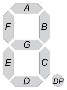
Basically for each 7-segment digit there are 8 pins: one for the common terminal (anode or cathode) and 7 pins for the 7 segments (A, B, C, D, E, F and G). Another pin may be used for the decimal point (DP).
In multi-digit 7-segment display (for example 4-digit) all pins of the same segment are connected together (segment A of digit 1 with segment A of digit 2 …), and each digit has its common pin alone. This is called multiplexing technique. This technique minimizes number of pins used.
So, for a 4-digit display we’ll have 7 pins of the 7 segments, 4 pins of the 4 digits (common terminals) and 1 pin for the decimal point (DP) which means a total of 12 pins.
Hardware Required:
- PIC18F46K22 microcontroller —-> datasheet
- 4-digit common anode 7-segment display
- 4 x PNP transistor (2SA1015, 2S9015, 2N3906 …)
- 7 x 100 ohm resistor
- 4 x 4.7k ohm resistor
- Push button
- 5V source
- Breadboard
- Jumper wires
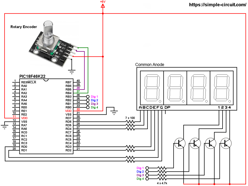
Interfacing PIC18F46K22 with 7-segment display circuit:
Project circuit schematic diagram is shown below.
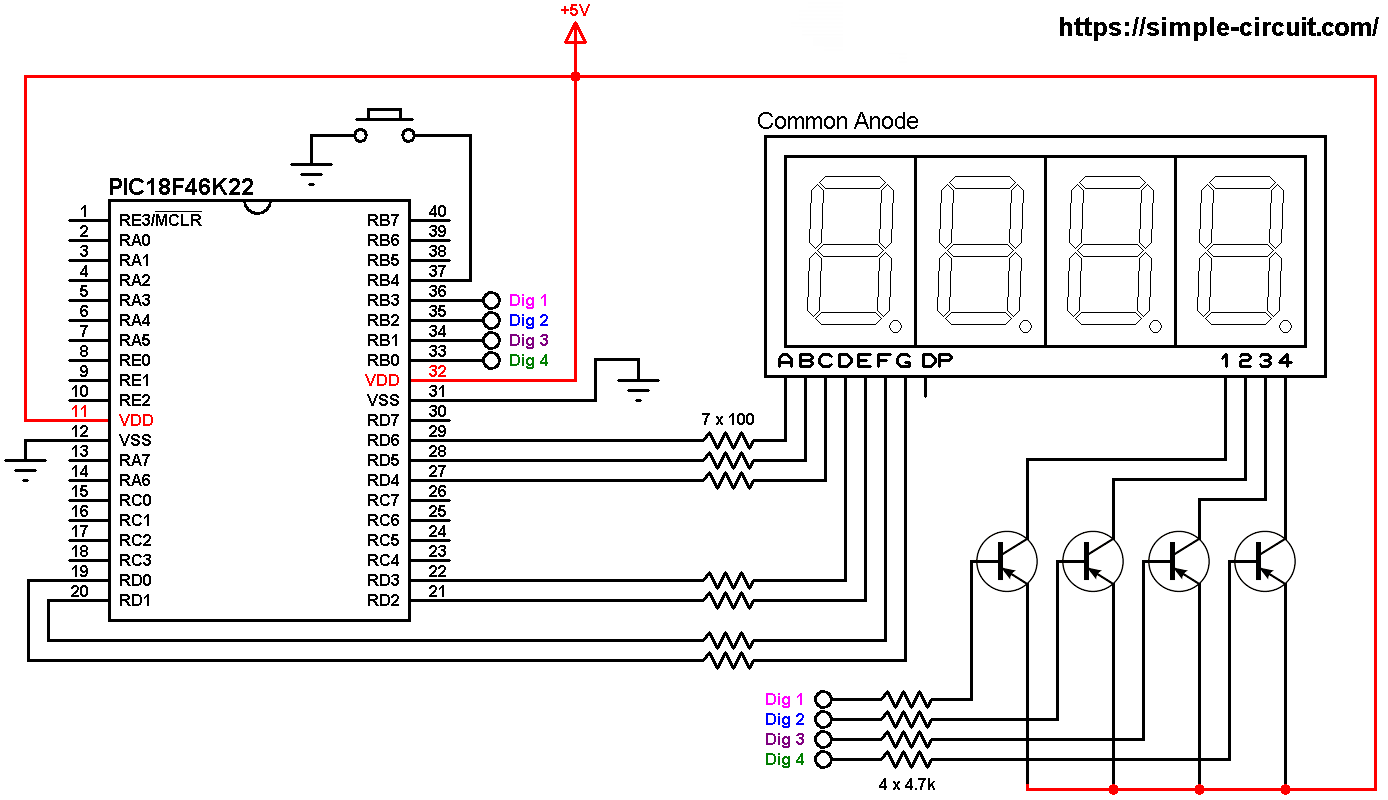
All the grounded terminals are connected together.
In the circuit there are 4 transistors of the type PNP, the collector of each transistor is connected to common anode pin of a single digit. That means each transistor supplies one digit segments.
The 4 transistors are used to supply the display LEDs with sufficient current because the PIC18F46K22 microcontroller may not be able to do that (maximum output current is 25 mA).
Each transistor emitter pin is connected to +5V and each transistor base is connected to the PIC18F46K22 through 4.7k resistor as follows:
digit 1 (most left) transistor base is connected to PIC18F46K22 pin RB3 (#36)
digit 2 transistor base is connected to PIC18F46K22 pin RB2 (#35)
digit 3 transistor base is connected to PIC18F46K22 pin RB1 (#34)
digit 4 (most right) transistor base is connected to PIC18F46K22 pin RB0 (#33)
Each 100 ohm resistor is used for limiting the current that passes through the segment LED.
The push button which is connected to PIC18F46K22 pin RB4 (#37) is used to increment the displayed number (internal weak pull-up is enabled in the C code).
Common anode 7-segment display is used in this example.
In this project the PIC18F46K22 microcontroller runs with its internal oscillator @ 8 MHz, MCLR pin is configured as an input pin.
Interfacing PIC18F46K22 with 7-segment display C code:
The following C code is for CCS C compiler, it was tested with version 5.051.
Since the 4 digits are multiplexed we need to refresh the display very quickly (display one digit at a time, others are off), for that I used Timer2 module (8-bit timer) interrupt with 1:16 prescaler and 1:2 postoscaler, this means Timer2 overflows every 2048 microseconds { 256/[8/(4 x 16)] = 256 x 8 = 2048 microseconds } and its interrupt occurred every 4096 microseconds (postoscaler = 2).
Timer2 module configuration is shown below (255 is the preload value):
1 | setup_timer_2( T2_DIV_BY_16, 255, 2 ); // enable Timer2 with prescaler=16 & postoscaler=2 |
CCS C Code:
1 2 3 4 5 6 7 8 9 10 11 12 13 14 15 16 17 18 19 20 21 22 23 24 25 26 27 28 29 30 31 32 33 34 35 36 37 38 39 40 41 42 43 44 45 46 47 48 49 50 51 52 53 54 55 56 57 58 59 60 61 62 63 64 65 66 67 68 69 70 71 72 73 74 75 76 77 78 79 80 81 82 83 84 85 86 87 88 89 90 91 92 93 94 95 96 97 98 99 100 101 102 103 104 105 106 107 108 109 110 111 112 113 114 | /* * Interfacing PIC18F46K22 with common anode 7-segment display. 4-Digit counter example. * C Code for CCS C compiler. * This is a free software with NO WARRANTY. * http://simple-circuit.com/ */ // counter button definition #define button PIN_B4 // segment pin definitions #define Seg_A PIN_D6 #define Seg_B PIN_D5 #define Seg_C PIN_D4 #define Seg_D PIN_D3 #define Seg_E PIN_D2 #define Seg_F PIN_D1 #define Seg_G PIN_D0 // common pins of the four digits definitions #define Com_1 PIN_B3 #define Com_2 PIN_B2 #define Com_3 PIN_B1 #define Com_4 PIN_B0 #include <18F46K22.h> #FUSES NOMCLR,NOLVP,NOBROWNOUT,PUT,NOXINST #use delay(internal = 8MHz) // variable declarations int16 count = 0; const char seg_maps[] = { 0x40, //0 0x79, //1 0x24, //2 0x30, //3 0x19, //4 0x12, //5 0x02, //6 0x78, //7 0x00, //8 0x10 //9 }; void seg_out(int8 nbr) { nbr = seg_maps[nbr]; output_bit(Seg_A, bit_test(nbr, 0)); output_bit(Seg_B, bit_test(nbr, 1)); output_bit(Seg_C, bit_test(nbr, 2)); output_bit(Seg_D, bit_test(nbr, 3)); output_bit(Seg_E, bit_test(nbr, 4)); output_bit(Seg_F, bit_test(nbr, 5)); output_bit(Seg_G, bit_test(nbr, 6)); } #INT_TIMER2 // Timer2 ISR void Timer2_ISR(void) { static int8 current_digit; // turn off all segments output_high(Com_1); output_high(Com_2); output_high(Com_3); output_high(Com_4); if(current_digit == 1) { seg_out(count / 1000); output_low(Com_1); // turn on digit 1 (most left) } if(current_digit == 2) { seg_out((count / 100) % 10); output_low(Com_2); // turn on digit 2 } if(current_digit == 3) { seg_out((count / 10) % 10); output_low(Com_3); // turn on digit 3 } if(current_digit == 4) { seg_out(count % 10); output_low(Com_4); // turn on digit 4 (most right) } current_digit = (current_digit % 4) + 1; } // main function void main() { setup_oscillator(OSC_8MHZ); // set internal oscillator to 8MHz port_b_pullups(0x10); // enable RB4 internal pull-up enable_interrupts(GLOBAL); // enable global interrupts clear_interrupt(INT_TIMER2); // clear Timer2 interrupt flag bit enable_interrupts(INT_TIMER2); // enable Timer2 interrupt setup_timer_2( T2_DIV_BY_16, 255, 2 ); // enable Timer2 with prescaler=16 & postoscaler=2 while(TRUE) { if( !input(button) ) { // if button is pressed count++; if(count > 9999) count = 0; delay_ms(200); // wait 200 milliseconds } } } // end of code. |
Hardware circuit of this example should be as the one shown below where Arduino uno board is used:
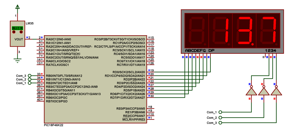
And Proteus simulation also should be the same:
Proteus simulation file download:
PIC18F46K22 7-segment display counter
Other PIC18F46K22 projects where 7-segment display is used:
Print ADC Values on 7-Segment Display with PIC18F46K22
Print rotary encoder values on 7-segment display with PIC18F46K22
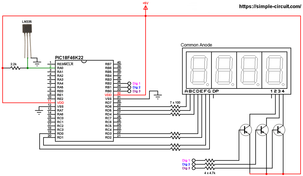
Interfacing PIC18F46K22 with LM335 sensor and 7-segment display
Interfacing PIC18F46K22 with 7-segment display and LM35 sensor
Discover more from Simple Circuit
Subscribe to get the latest posts sent to your email.