This PIC18F46K22 microcontroller project shows how to read analog voltages from an analog channel (using ADC module) and print the correspondent digital values on a multiplexed 4-digit 7-segment display. A potentiometer is used to get a voltage that varies between 0 and 5V. A common anode 7-segment display is used in this example.
The compiler used in this project is CCS C.
To see how to interface PIC18F46K22 microcontroller with 7-segment display (4-digit counter example), visit the following post:
Interfacing PIC18F46K22 with 7-segment display | 4-Digit counter example
Components Required:
- PIC18F46K22 microcontroller —-> datasheet
- 4-digit common anode 7-segment display
- 4 x PNP transistor (2SA1015, 2S9015, 2N3906 …)
- 10k ohm potentiometer
- 7 x 100 ohm resistor
- 4 x 4.7k ohm resistor
- 5V source
- Breadboard
- Jumper wires
- PIC MCU Programmer (PICkit 3, PICkit 4…)
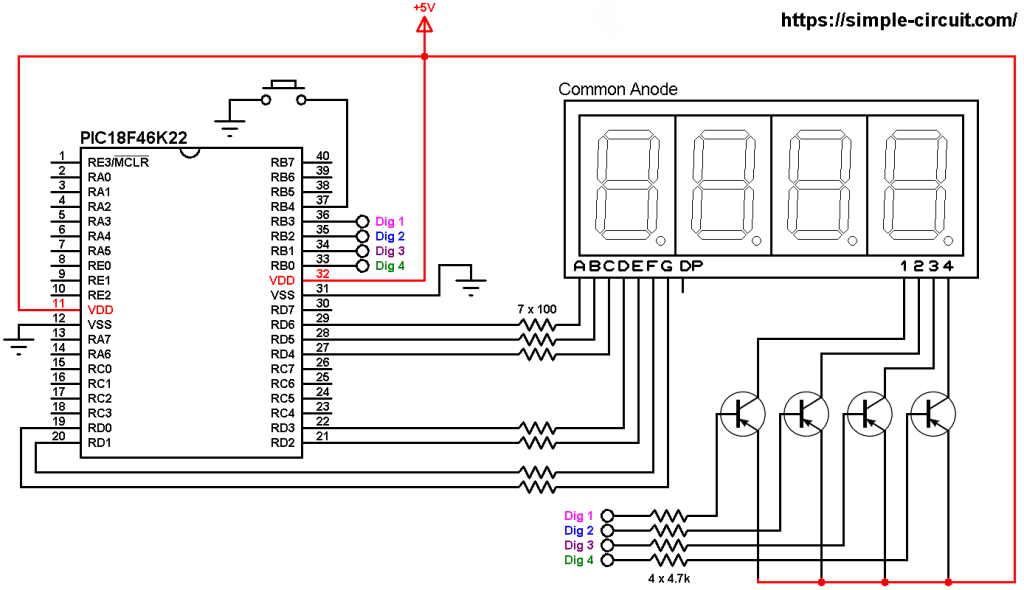
Print ADC values on 7-segment display with PIC18F46K22 circuit:
The following image shows example circuit diagram.

All the grounded terminals are connected together.
The four transistors used in this example are of the same type (PNP).
The potentiometer has 3 pins VCC , output and GND where:
VCC is connected to +5V
The output pin is connected to PIC18F46K22 analog channel 0 (AN0)
GND is connected to circuit ground.
In this project the PIC18F46K22 microcontroller runs with its internal oscillator @ 8 MHz, MCLR pin is configured as an input pin.
Print ADC values on 7-segment display with PIC18F46K22 C code:
The following C code is for CCS C compiler, it was tested with version 5.051.
The PIC18F46K22 ADC (Analog-to-Digital Converter)module reads analog voltage applied to analog channel AN0 (#2) and convert it to a digital representation which is then printed on the 7-segment display.
The PIC18F46K22 microcontroller has a built-in ADC module with 10-bit resolution. With a positive reference voltage of VCC (+5V), a 0V is represented by 0 and 5V is represented by a digital value of 1023.
Since the 4 digits are multiplexed we need to refresh the display very quickly (display one digit at a time, others are off), for that I used Timer2 module (8-bit timer) interrupt with 1:16 prescaler and 1:2 postoscaler, this means Timer2 overflows every 2048 microseconds { 256/[8/(4 x 16)] = 256 x 8 = 2048 microseconds } and its interrupt occurred every 4096 microseconds (postoscaler = 2).
Timer2 module configuration is shown below (255 is the preload value):
1 | setup_timer_2( T2_DIV_BY_16, 255, 2 ); // enable Timer2 with prescaler=16 & postoscaler=2 |
CCS C Code:
1 2 3 4 5 6 7 8 9 10 11 12 13 14 15 16 17 18 19 20 21 22 23 24 25 26 27 28 29 30 31 32 33 34 35 36 37 38 39 40 41 42 43 44 45 46 47 48 49 50 51 52 53 54 55 56 57 58 59 60 61 62 63 64 65 66 67 68 69 70 71 72 73 74 75 76 77 78 79 80 81 82 83 84 85 86 87 88 89 90 91 92 93 94 95 96 97 98 99 100 101 102 103 104 105 106 107 108 | /* * Interfacing PIC18F46K22 microcontroller with 7-segment display. * Print ADC values on common anode 4-digit 7-segment display. * C Code for CCS C compiler. * This is a free software with NO WARRANTY. * http://simple-circuit.com/ */ // segment pin definitions #define Seg_A PIN_D6 #define Seg_B PIN_D5 #define Seg_C PIN_D4 #define Seg_D PIN_D3 #define Seg_E PIN_D2 #define Seg_F PIN_D1 #define Seg_G PIN_D0 // common pins of the four digits definitions #define Com_1 PIN_B3 #define Com_2 PIN_B2 #define Com_3 PIN_B1 #define Com_4 PIN_B0 #include <18F46K22.h> #device ADC = 10 #fuses NOMCLR,NOLVP,NOBROWNOUT,PUT,NOXINST #use delay(internal = 8MHz) // variable declarations int16 adc_value = 0; const char seg_maps[] = { 0x40, //0 0x79, //1 0x24, //2 0x30, //3 0x19, //4 0x12, //5 0x02, //6 0x78, //7 0x00, //8 0x10 //9 }; void seg_out(int8 nbr) { nbr = seg_maps[nbr]; output_bit(Seg_A, bit_test(nbr, 0)); output_bit(Seg_B, bit_test(nbr, 1)); output_bit(Seg_C, bit_test(nbr, 2)); output_bit(Seg_D, bit_test(nbr, 3)); output_bit(Seg_E, bit_test(nbr, 4)); output_bit(Seg_F, bit_test(nbr, 5)); output_bit(Seg_G, bit_test(nbr, 6)); } #INT_TIMER2 // Timer2 ISR void Timer2_ISR(void) { static int8 current_digit; // turn off all segments output_high(Com_1); output_high(Com_2); output_high(Com_3); output_high(Com_4); if(current_digit == 1) { seg_out(adc_value / 1000); output_low(Com_1); // turn on digit 1 (most left) } if(current_digit == 2) { seg_out((adc_value / 100) % 10); output_low(Com_2); // turn on digit 2 } if(current_digit == 3) { seg_out((adc_value / 10) % 10); output_low(Com_3); // turn on digit 3 } if(current_digit == 4) { seg_out(adc_value % 10); output_low(Com_4); // turn on digit 4 (most right) } current_digit = (current_digit % 4) + 1; } // main function void main() { setup_oscillator(OSC_8MHZ); // set internal oscillator to 8MHz setup_adc(ADC_CLOCK_INTERNAL); // set ADC module clock to internal setup_adc_ports(sAN0); // configure RA0 (AN0) pin as analog set_adc_channel(sAN0); // select AN0 channel enable_interrupts(GLOBAL); // enable global interrupts clear_interrupt(INT_TIMER2); // clear Timer2 interrupt flag bit enable_interrupts(INT_TIMER2); // enable Timer2 interrupt setup_timer_2( T2_DIV_BY_16, 255, 2 ); // enable Timer2 with prescaler=16 & postoscaler=2 while(TRUE) { adc_value = read_adc(); // read data delay_ms(100); // wait 100 milliseconds } } // end of code. |
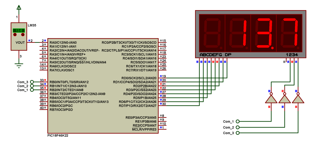
Hardware circuit of this example should be as the one shown below where Arduino uno board is used:
Discover more from Simple Circuit
Subscribe to get the latest posts sent to your email.