This small post shows how to make a temperature measurement station using PIC18F46K22 microcontroller and LM35 analog temperature sensor where temperature value is displayed on a three-digit common anode seven-segment display.
CCS C Compiler is used in this project
The LM35 temperature sensor is a three pin device (VCC, OUT and GND) with an output voltage linearly related to Centigrade temperature. Since the LM35 output varies with dependent to the temperature, we need an ADC (Analog-to-Digital Converter) module to measure this voltage. The PIC18F46K22 microcontroller has one ADC module with 10-bit resolution.
The LM35 output has linear +10mV/°C scale factor means the following:
If the output voltage = 10mV —> temperature = 1°C
If the output voltage = 100mV —> temperature = 10°C
If the output voltage = 200mV —> temperature = 20°C
If the output voltage = 370mV —> temperature = 37°C
and so on.
LM35 Futures (from datasheet):
- Calibrated Directly in ° Celsius (Centigrade)
- Linear + 10 mV/°C Scale Factor
- 0.5°C Ensured Accuracy (at +25°C)
- Rated for Full −55°C to +150°C Range
- Suitable for Remote Applications
- Low Cost Due to Wafer-Level Trimming
- Operates from 4 to 30 V
- Less than 60-μA Current Drain
- Low Self-Heating, 0.08°C in Still Air
- Nonlinearity Only ±¼°C Typical
- Low Impedance Output, 0.1 Ω for 1 mA Load
The ADC module converts analog data into digital data. The PIC18F46K22 MCU has a 10-bit ADC module and a built-in fixed voltage reference (FVR) module which makes it a good choice for this application. With the fixed voltage reference we get a very good result.
Normally negative and positive references of the ADC module are VSS and VDD respectively, but VDD is not exactly equal to 5.00V, hence we should use the fixed voltage reference as a positive reference of the ADC module.
The PIC18F46K22 has 3 fixed voltage references: 1.024V, 2.048V and 4.096V. For example if we set the fixed voltage reference to 4.096V and the ADC module is configured so that the negative and the positive references are VSS and FVR respectively, in this case the equivalent 10-bit digital value of 4.096 is 1023 and 3.00V is 3.00 * 1023/4.096 = 749 , and so on.
In this project I used FVR = 1.024V because the LM35 output is generally less than 1V and also it gave me better result (let’s say higher resolution). Now the ADC module works in the interval between 0 and 1.024V.
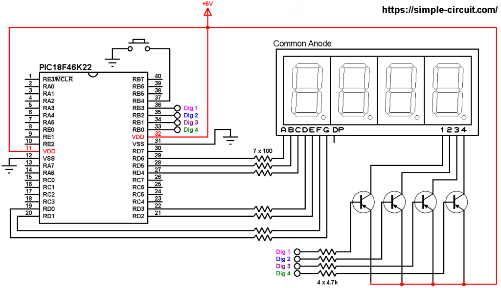
The value of the temperature is displayed on 3-digit common anode 7-segment display, to see how to interface the PIC18F46K22 microcontroller with 7-segment display (4-digit counter example), visit the following post:
Interfacing PIC18F46K22 with 7-segment display | 4-Digit counter example
Parts Required:
- PIC18F46K22 microcontroller —-> datasheet
- 3 or 4-digit common anode 7-segment display
- LM35 temperature sensor —-> datasheet
- 3 x PNP transistor (2SA1015, 2S9015, 2N3906 …)
- 8 x 100 ohm resistor
- 3 x 4.7k ohm resistor
- 5V source
- Breadboard
- Jumper wires
- PIC MCU Programmer (PICkit 3, PICkit 4…)
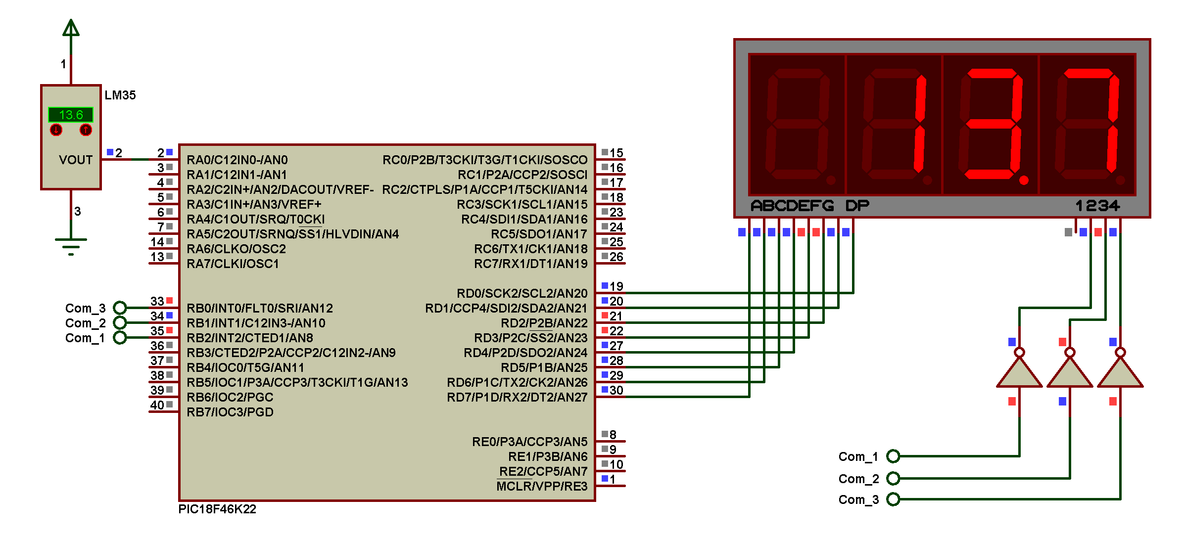
PIC18F46K22 with LM35 sensor and 7-segment display circuit:
Project circuit schematic diagram is shown below.
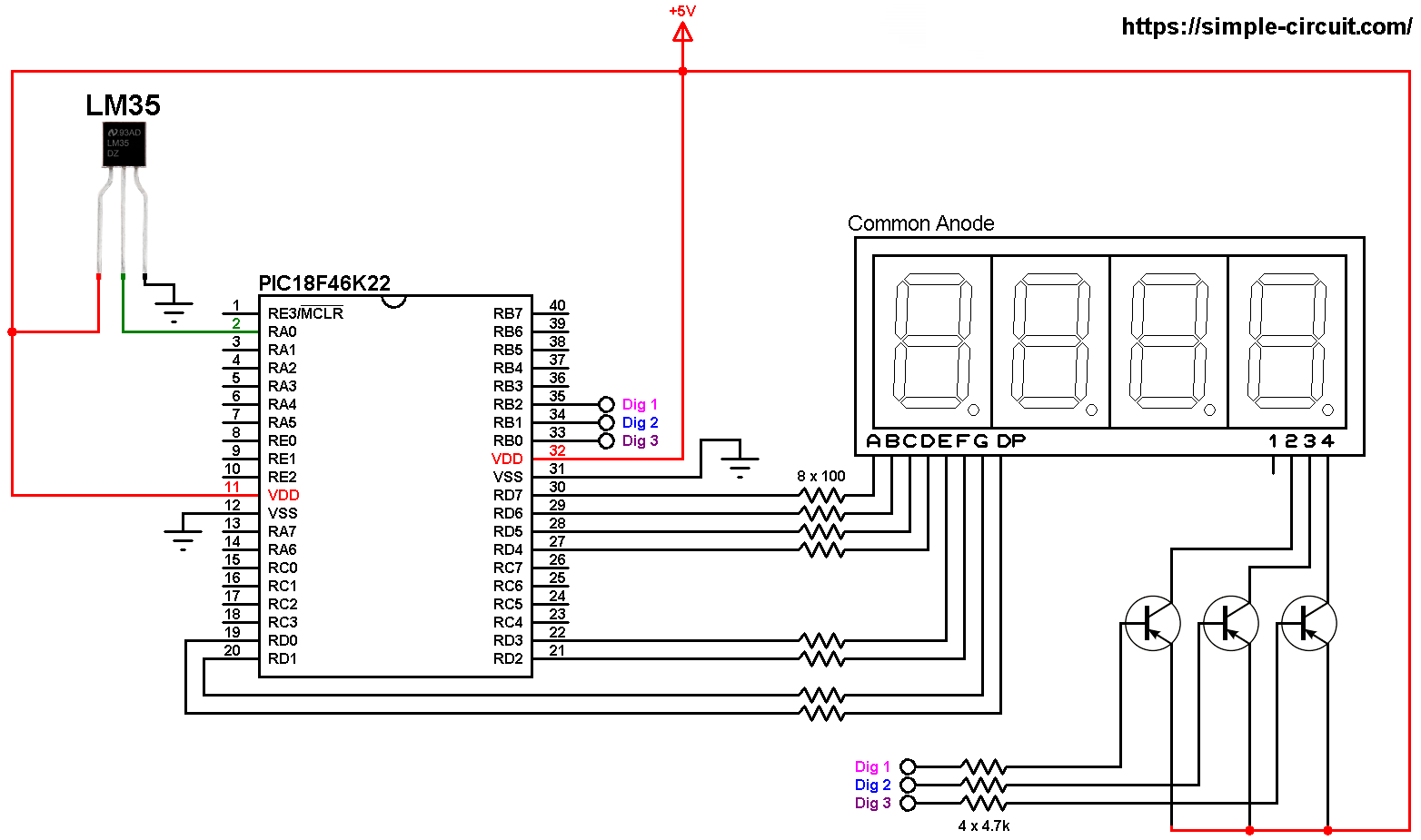
All the grounded terminals are connected together.
The LM35 sensor has 3 pins (from left to right):
Pin 1 is power supply pin, connected to circuit +5V
Pin 2: output pin
Pin 3: GND (ground), connected to circuit ground.
The output pin of the LM35 sensor is connected to pin RA0 which is analog channel 0 (AN0).
The 3 transistors are of the same type (PNP).
In this project the PIC18F46K22 microcontroller runs with its internal oscillator @ 8 MHz, MCLR pin is configured as an input pin.
PIC18F46K22 with LM35 sensor and 7-segment display C code:
The following C code is for CCS C compiler, it was tested with version 5.051.
The internal fixed voltage reference (FVR) of the PIC18F46K22 microcontroller is set to 1.024V using the following line:
1 | setup_vref(VREF_1v024); // set FVR to 1.024V // FVR: Fixed Voltage Reference |
The ADC module is configured so that it uses its internal clock, voltage references (negative and positive) are set to VSS and FVR respectively where the FVR is the one previously set to 1.024V.
The LM35 output pin is connected to AN0 channel. All these configurations are done in the code as shown below:
1 2 3 | setup_adc(ADC_CLOCK_INTERNAL); // set ADC module clock to internal setup_adc_ports(sAN0 | VSS_FVR); // configure AN0 pin as analog & Voltage references: VSS-FVR set_adc_channel(sAN0); // select AN0 channel |
PIC18F46K22 ADC module is used with 10-bit resolution which means the digital value of the input analog voltage varies between 0 (for 0V) and 1023 (for 1.024V). The digital value also represents the temperature in tenths °Celsius (output value of “274” equals 27.4 °Celsius).
CCS C Code:
1 2 3 4 5 6 7 8 9 10 11 12 13 14 15 16 17 18 19 20 21 22 23 24 25 26 27 28 29 30 31 32 33 34 35 36 37 38 39 40 41 42 43 44 45 46 47 48 49 50 51 52 53 54 55 56 57 58 59 60 61 62 63 64 65 66 67 68 69 70 71 72 73 74 75 76 77 78 79 80 81 82 83 84 85 86 87 88 89 90 91 92 93 94 95 96 97 98 99 100 101 102 103 104 105 106 107 | /* * Interfacing PIC18F46K22 MCU with LM35 temperature sensor and 7-segment display. * Common anode 7-segment display is used. * C Code for CCS C compiler. * This is a free software with NO WARRANTY. * http://simple-circuit.com/ */ // segment pin definitions #define Seg_A PIN_D7 #define Seg_B PIN_D6 #define Seg_C PIN_D5 #define Seg_D PIN_D4 #define Seg_E PIN_D3 #define Seg_F PIN_D2 #define Seg_G PIN_D1 #define Seg_DP PIN_D0 // common pins of the three digits definitions #define Com_1 PIN_B2 #define Com_2 PIN_B1 #define Com_3 PIN_B0 #include <18F46K22.h> #device ADC = 10 #fuses NOMCLR,NOLVP,NOBROWNOUT,PUT,NOXINST #use delay(internal = 8MHz) // variable declarations int16 temp; const char seg_maps[] = { 0x40, // 0 0x79, // 1 0x24, // 2 0x30, // 3 0x19, // 4 0x12, // 5 0x02, // 6 0x78, // 7 0x00, // 8 0x10 // 9 }; void seg_out(int8 nbr) { nbr = seg_maps[nbr]; output_bit(Seg_A, bit_test(nbr, 0)); output_bit(Seg_B, bit_test(nbr, 1)); output_bit(Seg_C, bit_test(nbr, 2)); output_bit(Seg_D, bit_test(nbr, 3)); output_bit(Seg_E, bit_test(nbr, 4)); output_bit(Seg_F, bit_test(nbr, 5)); output_bit(Seg_G, bit_test(nbr, 6)); } #INT_TIMER2 // Timer2 ISR void Timer2_ISR(void) { static int8 current_digit; // turn off all segments output_high(Com_1); output_high(Com_2); output_high(Com_3); output_high(Seg_DP); if(current_digit == 1) { seg_out( (temp / 100) % 10 ); output_low(Com_1); // turn on digit 1 (most left) } if(current_digit == 2) { seg_out( (temp / 10) % 10 ); output_low(Seg_DP); // print decimal point output_low(Com_2); // turn on digit 2 } if(current_digit == 3) { seg_out(temp % 10); output_low(Com_3); // turn on digit 3 (most right) } current_digit = (current_digit % 3) + 1; } // main function void main() { setup_oscillator(OSC_8MHZ); // set internal oscillator to 8MHz setup_vref(VREF_1v024); // set FVR to 1.024V // FVR: Fixed Voltage Reference setup_adc(ADC_CLOCK_INTERNAL); // set ADC module clock to internal setup_adc_ports(sAN0 | VSS_FVR); // configure AN0 pin as analog & Voltage references: VSS - FVR(1.024V) set_adc_channel(sAN0); // select AN0 channel enable_interrupts(GLOBAL); // enable global interrupts clear_interrupt(INT_TIMER2); // clear Timer2 interrupt flag bit enable_interrupts(INT_TIMER2); // enable Timer2 interrupt setup_timer_2( T2_DIV_BY_16, 255, 2 ); // enable Timer2 with prescaler=16 & postoscaler=2 while(TRUE) { // read analog voltage temp = read_adc(); delay_ms(1000); // wait 1 second } } // end of code. |
Proteus simulation of the project should give a result near to the one shown below where Arduino UNO board is used (simulation circuit is not the same as real hardware circuit, project hardware circuit is shown above):
Proteus simulation file download:
PIC18F46K22 + LM35 sensor + 7-segment display
Discover more from Simple Circuit
Subscribe to get the latest posts sent to your email.