This post shows how to build a simple real time clock/calendar using PIC18F46K22 microcontroller and DS1307 RTC chip where time and date are displayed on 20×4 LCD screen and they could be set using two push buttons connected to the PIC18F46K22 microcontroller.
The compiler used in this project is CCS PIC C.
Hardware Required:
- PIC18F46K22 microcontroller —-> datasheet
- 20×4 LCD screen
- DS1307 RTC —-> datasheet
- 32.768 kHz crystal oscillator
- 2 x 10k ohm resistor
- 330 ohm resistor
- 2 x push button
- 10k ohm variable resistor or potentiometer
- 3V coin cell battery
- 5V power source
- Breadboard
- Jumper wires
Interfacing PIC18F46K22 with DS1307 and 20×4 LCD circuit:
The following image shows project circuit schematic diagram.
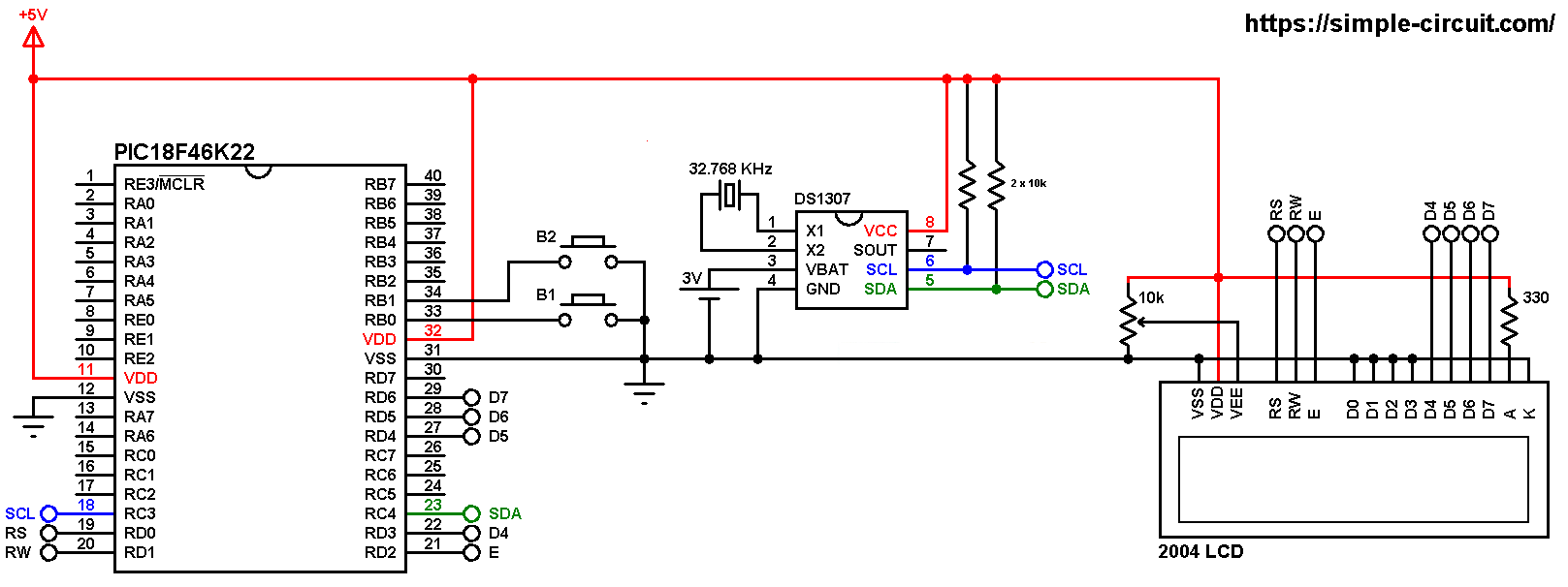
All grounded terminals are connected together.
The two push buttons in the circuit are used to set time and date of the real time clock, button 1 (B1) is connected to RB0 pin (#33) and button 2 (B2) is connected to RB1 pin (#34).
SCL and SDA pins of DS1307 are respectively connected to PIC18F46K22 pins RC3 (#18) and RC4 (#23) which are hardware I2C module pins (MSSP1).
The 20×4 LCD screen is connected to the PIC18F46K22 microcontroller as follows:
RS —> RD0 pin
RW —> RD1 pin
E —> RD2 pin
D4 —> RD3 pin
D5 —> RD4 pin
D6 —> RD5 pin
D7 —> RD6 pin
VSS, D0, D1, D2, D3 and K are connected to circuit GND (ground).
VEE to the variable resistor (or potentiometer) output pin.
VDD to +5V and A to +5V through 330 ohm resistor.
VEE pin is used to control the contrast of the LCD. A (anode) and K (cathode) are the back light LED pins.
In this project the PIC18F46K22 microcontroller runs with its internal oscillator @ 8 MHz, MCLR pin is configured as an input pin.
Interfacing PIC18F46K22 with DS1307 and 20×4 LCD C code:
The following C code is for CCS C compiler, it was tested with version 5.051.
To be able to compile the C code below, a driver (library) for DS1307 RTC is required, its full name (with extension) is DS1307.C, download link is the one below:
DS1307 CCS C driver
After the download, add it to project folder or CCS C drivers folder (for example C:\Program Files (x86)\CCS\Drivers).
For more information about DS1307 driver for CCS C compiler, visit the following post:
DS1307 RTC driver for CCS C compiler
I2C Bus (using I2C1 module) is initialized in the code as shown below at clock frequency of 100kHz:
1 | #use I2C(MASTER, I2C1, SLOW = 100000, STREAM = DS1307_STREAM) |
Functions used in the code:
int1 debounce (): this function is for button B1 debounce, returns 1 if button is debounced.
void dow_print(): displays day of the week (Monday, Tuesday …) on the LCD.
void rtc_print(): displays time, date and day of the week on the LCD. This function calls the previous one for displaying the day of the week.
void wait(): this function is just a delay of 500 ms except that it can be interrupted by the two push buttons (B1 and B2). In this function Timer0 module is used to count the 500 milliseconds, it is used as 16-bit timer with prescaler = 16 (==> 1 tick every 8 microseconds ==> 62500 x 8 = 500000 us = 500 ms).
int8 edit(int8 x_pos, int8 y_pos, int8 parameter): this function is for setting the real time clock, returns the edited parameter.
Rest of code is described through comments.
Full CCS C code:
1 2 3 4 5 6 7 8 9 10 11 12 13 14 15 16 17 18 19 20 21 22 23 24 25 26 27 28 29 30 31 32 33 34 35 36 37 38 39 40 41 42 43 44 45 46 47 48 49 50 51 52 53 54 55 56 57 58 59 60 61 62 63 64 65 66 67 68 69 70 71 72 73 74 75 76 77 78 79 80 81 82 83 84 85 86 87 88 89 90 91 92 93 94 95 96 97 98 99 100 101 102 103 104 105 106 107 108 109 110 111 112 113 114 115 116 117 118 119 120 121 122 123 124 125 126 127 128 129 130 131 132 133 134 135 136 137 138 139 140 141 142 143 144 145 146 147 148 149 150 151 152 153 154 155 156 157 158 159 160 161 162 163 164 165 166 167 168 169 170 171 172 173 174 175 176 177 178 179 180 181 182 183 | /* * Interfacing PIC18F46K22 microcontroller with DS1307 RTC. * C Code for CCS C compiler. * This is a free software with NO WARRANTY. * http://simple-circuit.com/ */ // LCD module connections #define LCD_RS_PIN PIN_D0 #define LCD_RW_PIN PIN_D1 #define LCD_ENABLE_PIN PIN_D2 #define LCD_DATA4 PIN_D3 #define LCD_DATA5 PIN_D4 #define LCD_DATA6 PIN_D5 #define LCD_DATA7 PIN_D6 // end LCD module connections // button definitions #define button1 PIN_B0 #define button2 PIN_B1 #include <18F46K22.h> #fuses NOMCLR,NOLVP,NOBROWNOUT,PUT,NOXINST #use delay(internal = 8MHz) #use I2C(MASTER, I2C1, SLOW = 100000, STREAM = DS1307_STREAM) #include <lcd.c> // include LCD driver source file #include <DS1307.c> // include DS1307 driver source file int8 i; // DS1307 library variable declaration RTC_Time *mytime; // function for displaying day of the week void dow_print() { lcd_gotoxy(6, 2); switch(mytime->dow) { case SUNDAY : printf(lcd_putc, " SUNDAY "); break; case MONDAY : printf(lcd_putc, " MONDAY "); break; case TUESDAY : printf(lcd_putc, " TUESDAY "); break; case WEDNESDAY: printf(lcd_putc, "WEDNESDAY"); break; case THURSDAY : printf(lcd_putc, "THURSDAY "); break; case FRIDAY : printf(lcd_putc, " FRIDAY "); break; default : printf(lcd_putc, "SATURDAY "); } } // function for printing time and date on LCD void rtc_print() { // print day of the week dow_print(); // print time lcd_gotoxy(21, 1); // move cursor to row 3, column 1 printf(lcd_putc, "TIME: %02u:%02u:%02u", mytime->hours, mytime->minutes, mytime->seconds); // print date lcd_gotoxy(21, 2); // move cursor to row 4, column 1 printf(lcd_putc, "DATE: %02u-%02u-20%02u", mytime->day, mytime->month, mytime->year); } // a small function for button1 (B1) debounce int1 debounce() { int8 count = 0; for(int8 i = 0; i < 5; i++) { if ( !input(button1) ) count++; delay_ms(10); } if(count > 2) return 1; else return 0; } void wait() { set_timer0(0); while( (get_timer0() < 62500L) && input(button1) && input(button2) ) ; } int8 edit(int8 x_pos, int8 y_pos, int8 parameter) { while(debounce()); // call debounce function (wait for B1 to be released) lcd_gotoxy(x_pos, y_pos); // move cursor to row y_pos, column x_pos while(TRUE) { while(!input(button2)) { parameter++; if(i == 0 && parameter > 23) // if hours > 23 ==> hours = 0 parameter = 0; if(i == 1 && parameter > 59) // if minutes > 59 ==> minutes = 0 parameter = 0; if(i == 2 && parameter > 31) // if day > 31 ==> day = 1 parameter = 1; if(i == 3 && parameter > 12) // if month > 12 ==> month = 1 parameter = 1; if(i == 4 && parameter > 99) // if year > 99 ==> year = 0 parameter = 0; printf(lcd_putc, "%02u\b\b", parameter); delay_ms(200); } lcd_putc(" \b\b"); wait(); printf(lcd_putc, "%02u\b\b", parameter); wait(); if(!input(button1)) // if button B1 is pressed { i++; // increment 'i' for the next parameter return parameter; // return parameter value and exit } } } // main function void main() { setup_oscillator(OSC_8MHZ); // set internal oscillator to 8MHz port_b_pullups(3); // enable RB0 & RB1 internal weak pull-ups delay_ms(1000); // wait a second lcd_init(); // initialize LCD module lcd_putc("\fPIC18F46K22 + DS1307"); OSC_Enable(); // enable DS1307 oscillator while(TRUE) { // read current time and date from the RTC chip mytime = RTC_Get(); // print all data rtc_print(); if(!input(button1)) // if button B1 is pressed if(debounce()) // call debounce function (make sure if B1 is pressed) { i = 0; while(debounce()); // call debounce function (wait for button B1 to be released) setup_timer_0(T0_INTERNAL | T0_DIV_16); // start Timer0 with internal clock & prescaler=16 while(TRUE) { while( !input(button2) ) // if button B2 button is pressed { mytime->dow++; if(mytime->dow > SATURDAY) mytime->dow = SUNDAY; dow_print(); // print week day delay_ms(500); } lcd_gotoxy(6, 2); lcd_putc(" "); wait(); // call wait() function dow_print(); // print week day wait(); // call wait() function if( !input(button1) ) // if button B1 is pressed break; } mytime->hours = edit(27, 1, mytime->hours); // edit hours mytime->minutes = edit(30, 1, mytime->minutes); // edit minutes mytime->day = edit(27, 2, mytime->day); // edit day (day of month) mytime->month = edit(30, 2, mytime->month); // edit month mytime->year = edit(35, 2, mytime->year); // edit year mytime->seconds = 0; // reset seconds setup_timer_0(T0_OFF); // disable Timer0 while(debounce()); // call debounce function (wait for button B1 to be released) // write data to the RTC chip RTC_Set(mytime); } delay_ms(100); // wait 100 ms } } // end of code. |
The following video shows Proteus simulation of this project (simulation circuit is not the same as real hardware circuit, project hardware circuit is shown above):
Proteus simulation file download:
PIC18F46K22 + DS1307 RTC + 20×4 LCD
Discover more from Simple Circuit
Subscribe to get the latest posts sent to your email.