This is another example that shows how to interface PIC18F46K22 microcontroller with common anode 7-segment display.
This example shows how to print rotary encoder values (positive and negative) on 4-digit 7-segment display where the first digit (most left) is used for the minus sign ( – ). Here the rotary encoder is an input device and the 7-segment display is an output device.
The compiler used in this project is CCS C.
To see how to interface PIC18F46K22 microcontroller with 7-segment display (4-digit counter example), visit the following post:
Interfacing PIC18F46K22 with 7-segment display | 4-Digit counter example
Components Required:
- PIC18F46K22 microcontroller —-> datasheet
- 4-digit common anode 7-segment display
- 4 x PNP transistor (2SA1015, 2S9015, 2N3906 …)
- Rotary encoder
- 7 x 100 ohm resistor
- 4 x 4.7k ohm resistor
- 5V source
- Breadboard
- Jumper wires
PIC18F46K22 with 7-segment display and rotary encoder circuit:
The image below shows our example circuit diagram.
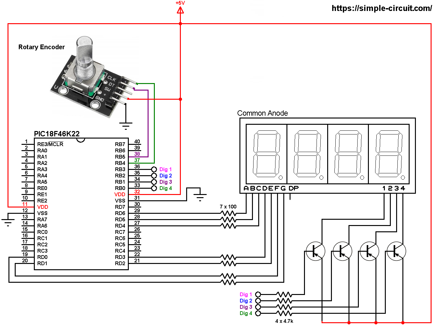
All the grounded terminals are connected together.
The rotary encoder board has 5 pins: GND, + , SW, DT (pin B or data pin) and CLK (pin A or clock pin) where:
GND is connected to circuit ground (0V)
+ is connected to +5V
SW is push button pin, not used in this example
DT is connected to PIC18F46K22 pin RB5 (#38)
CLK is connected to PIC18F46K22 pin RB4 (#37)
The 4 transistors are of the same type (PNP).
In this project the PIC18F46K22 microcontroller runs with its internal oscillator @ 8 MHz, MCLR pin is configured as an input pin.
PIC18F46K22 with 7-segment display and rotary encoder C code:
The following C code is for CCS C compiler, it was tested with version 5.051.
Since the 4 digits are multiplexed we need to refresh the display very quickly (display one digit at a time, others are off), for that I used Timer2 module (8-bit timer) interrupt with 1:16 prescaler and 1:2 postoscaler, this means Timer2 overflows every 2048 microseconds { 256/[8/(4 x 16)] = 256 x 8 = 2048 microseconds } and its interrupt occurred every 4096 microseconds (postoscaler = 2).
Timer2 module configuration is shown below (255 is the preload value):
1 | setup_timer_2( T2_DIV_BY_16, 255, 2 ); // enable Timer2 with prescaler=16 & postoscaler=2 |
PORTB interrupt-on-change is enabled for pins RB4 and RB5 which are respectively connected to CLK and DT pins of the rotary encoder. This interrupt detects falling and rising of the two lines:
1 2 | enable_interrupts(INT_RB); // enable RB IOC IOCB = 0x30; // enable RB4 & RB5 IOC |
Rest of code is described through comments.
CCS C Code:
1 2 3 4 5 6 7 8 9 10 11 12 13 14 15 16 17 18 19 20 21 22 23 24 25 26 27 28 29 30 31 32 33 34 35 36 37 38 39 40 41 42 43 44 45 46 47 48 49 50 51 52 53 54 55 56 57 58 59 60 61 62 63 64 65 66 67 68 69 70 71 72 73 74 75 76 77 78 79 80 81 82 83 84 85 86 87 88 89 90 91 92 93 94 95 96 97 98 99 100 101 102 103 104 105 106 107 108 109 110 111 112 113 114 115 116 117 118 119 120 121 122 123 124 125 126 127 128 129 130 131 132 133 134 135 136 137 138 139 140 141 142 143 144 145 146 147 148 149 150 151 152 153 154 | /* * Interfacing PIC18F46K22 microcontroller with 7-segment display. * Print rotary encoder values on common anode 4-digit 7-segment display. * C Code for CCS C compiler. * This is a free software with NO WARRANTY. * http://simple-circuit.com/ */ // segment pin definitions #define Seg_A PIN_D6 #define Seg_B PIN_D5 #define Seg_C PIN_D4 #define Seg_D PIN_D3 #define Seg_E PIN_D2 #define Seg_F PIN_D1 #define Seg_G PIN_D0 // common pins of the four digits definitions #define Com_1 PIN_B3 #define Com_2 PIN_B2 #define Com_3 PIN_B1 #define Com_4 PIN_B0 #include <18F46K22.h> #fuses NOMCLR,NOLVP,NOBROWNOUT,PUT,NOXINST #use delay(internal = 8MHz) #use fast_io(B) #use fast_io(D) #BYTE IOCB = 0x0F62 // 0x0F62: IOCB register address // variable declarations int8 last_read; signed int8 quad = 0, change; signed int16 enc_value = 0; const char seg_maps[] = { 0x40, // 0 0x79, // 1 0x24, // 2 0x30, // 3 0x19, // 4 0x12, // 5 0x02, // 6 0x78, // 7 0x00, // 8 0x10, // 9 0x3F // - }; void seg_out(int8 nbr) { nbr = seg_maps[nbr]; output_bit(Seg_A, bit_test(nbr, 0)); output_bit(Seg_B, bit_test(nbr, 1)); output_bit(Seg_C, bit_test(nbr, 2)); output_bit(Seg_D, bit_test(nbr, 3)); output_bit(Seg_E, bit_test(nbr, 4)); output_bit(Seg_F, bit_test(nbr, 5)); output_bit(Seg_G, bit_test(nbr, 6)); } #INT_RB // PORTB interrupt on change ISR void RB_IOC_ISR(void) { int8 encoderRead; clear_interrupt(INT_RB); // clear RB IOC flag encoderRead = input_b() & 0x30; if(encoderRead == last_read) return; if(bit_test(encoderRead, 4) == bit_test(last_read, 5)) quad -= 1; else quad += 1; last_read = encoderRead; } #INT_TIMER2 // Timer2 ISR void Timer2_ISR(void) { static int8 current_digit; int16 abs_value = abs(enc_value); // abs: absolute value // turn off all segments output_high(Com_1); output_high(Com_2); output_high(Com_3); output_high(Com_4); if( (current_digit == 1) && (enc_value < 0) ) { // if the value is negative seg_out(10); // print minus sign (-) output_low(Com_1); // turn on digit 1 (most left) } if(current_digit == 2) { seg_out((abs_value / 100) % 10); output_low(Com_2); // turn on digit 2 } if(current_digit == 3) { seg_out((abs_value / 10) % 10); output_low(Com_3); // turn on digit 3 } if(current_digit == 4) { seg_out(abs_value % 10); output_low(Com_4); // turn on digit 4 (most right) } current_digit = (current_digit % 4) + 1; } signed int8 EncoderGet(void) { signed int8 value = 0; while(quad >= 4) { value += 1; quad -= 4; } while(quad <= -4) { value -= 1; quad += 4; } return value; } // main function void main() { setup_oscillator(OSC_8MHZ); // set internal oscillator to 8MHz set_tris_b(0xF0); // configure RB0 ~ 3 pins as outputs set_tris_d(0); // configure all PORTD pins as outputs enable_interrupts(GLOBAL); // enable global interrupts clear_interrupt(INT_TIMER2); // clear Timer2 interrupt flag bit enable_interrupts(INT_TIMER2); // enable Timer2 interrupt setup_timer_2( T2_DIV_BY_16, 255, 2 ); // enable Timer2 with prescaler=16 & postoscaler=2 clear_interrupt(INT_RB); // clear RB IOC flag enable_interrupts(INT_RB); // enable RB IOC IOCB = 0x30; // enable RB4 & RB5 IOC last_read = input_b() & 0x30; while(TRUE) { change = EncoderGet(); if(change) enc_value += change; delay_ms(100); // wait 100 milliseconds } } // end of code. |
The hardware circuit of this project should give a result similar to the one shown in the following video where Arduino UNO board is used:
Discover more from Simple Circuit
Subscribe to get the latest posts sent to your email.