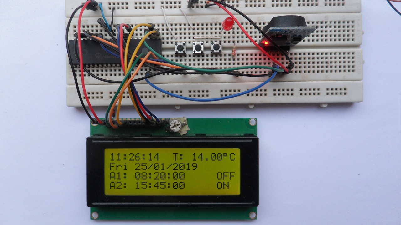
This post shows how to build real time clock/calendar with 2 alarm functions using PIC18F46K22 microcontroller and DS3231 RTC chip. Time, date and alarms are displayed on 20×4 LCD screen.
In the circuit there will be 3 push buttons for setting time, date and alarms, and one LED for indicating the alarms when occurred.
The compiler used in this project is CCS PIC C.
The DS3231 RTC has built-in two alarm functions and a temperature sensor with a resolution of 0.25 °C and an accuracy of ±3 °C. Also, chip temperature will be displayed on the 20×4 LCD.
Hardware Required:
- PIC18F46K22 microcontroller —-> datasheet
- 20×4 LCD screen
- DS3231 board —> DS3231 datasheet
- 3 x push button
- 2 x 330 ohm resistor
- LED
- 10k ohm variable resistor or potentiometer
- 3V coin cell battery
- 5V power source
- Breadboard
- Jumper wires
PIC18F46K22 with DS3231 and LCD circuit:
The following image shows project hardware circuit diagram.
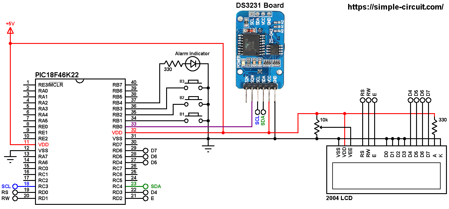
All the grounded terminals are connected together.
The DS3231 board is supplied with 5V as the 2004 LCD and the PIC18F46K22 microcontroller, there are 3 data lines connected between this board and the microcontroller, SCL line is connected to pin RC3 (#18), SDA line is connected to pin RC4 (#23) and INT (interrupt) line is connected to external interrupt pin RB0 (#33). The DS3231 interrupts the microcontroller when there is an alarm (alarm 1 or alarm 2).
In the circuit there are 3 push buttons: B1, B2 and B3. These buttons are used to set time, date and alarms. Time and date are set with B1 and B2 where button B1 selects time or date parameter (time parameters: hours and minutes; date parameters: day of the week, date, month and year) and B2 increments the selected parameter. Buttons B3 and B2 set alarm 1 and alarm 2 parameters (hours, minutes and ON/OFF), button B3 selects the parameter and B2 increments the selected parameter.
Also, there is an LED connected to PIC18F46K22 pin RB4 (#37), this LED is used as an alarm indicator (alarm 1 or alarm 2), so if there is an alarm, the DS3231 pulls down the INT line (RB0) which interrupts the microcontroller and the microcontroller turns the LED ON, here button B2 turns both the LED and the occurred alarm OFF.
The 20×4 LCD screen is connected to the PIC18F46K22 microcontroller as follows:
RS —> RD0 pin
RW —> RD1 pin
E —> RD2 pin
D4 —> RD3 pin
D5 —> RD4 pin
D6 —> RD5 pin
D7 —> RD6 pin
VSS, D0, D1, D2, D3 and K are connected to circuit GND (ground).
VEE to the variable resistor (or potentiometer) output pin.
VDD to +5V and A to +5V through 330 ohm resistor.
VEE pin is used to control the contrast of the LCD. A (anode) and K (cathode) are the back light LED pins.
In this project the PIC18F46K22 microcontroller runs with its internal oscillator @ 8 MHz, MCLR pin is configured as an input pin.
PIC18F46K22 with DS3231 and LCD C code:
The following C code is for CCS C compiler, it was tested with version 5.051.
To be able to compile the C code below, a driver (library) for DS3231 RTC is required, its full name (with extension) is DS3231.C, download link is the one below:
DS3231 CCS C driver
After the download, add it to project folder or CCS C drivers folder (for example C:\Program Files (x86)\CCS\Drivers).
For more information about DS3231 driver for CCS C compiler, visit the following post:
DS3231 RTC driver for CCS C compiler
I2C Bus (using I2C1 module) is initialized in the code as shown below at clock frequency of 100kHz:
1 | #use I2C(MASTER, I2C1, SLOW = 100000, STREAM = DS3231_STREAM) |
Functions used in the code:
int1 debounce (): this function is for button B1 debounce, returns 1 if button is debounced.
void dow_print(): displays day of the week (Monday, Tuesday …) on the LCD.
void wait(): this function is just a delay of 500 ms except that it can be interrupted by the three push buttons (B1, B2 and B3). In this function Timer0 module is used to count the 500 milliseconds, it is used as 16-bit timer with prescaler = 16 (==> 1 tick every 8 microseconds ==> 62500 x 8 = 500000 us = 500 ms).
int8 edit(int8 x_pos, int8 y_pos, int8 parameter): this function is for setting the real time clock, returns the edited parameter.
void alarms_edit(int8 _alarm): this function is for setting the status of alarm 1 and alarm 2 (ON or OFF). If the variable _alarm = 1 the alarm will be set is alarm 1, and if _alarm = 2 the alarm will be set is alarm 2.
Rest of code is described through comments.
Full CCS C code:
1 2 3 4 5 6 7 8 9 10 11 12 13 14 15 16 17 18 19 20 21 22 23 24 25 26 27 28 29 30 31 32 33 34 35 36 37 38 39 40 41 42 43 44 45 46 47 48 49 50 51 52 53 54 55 56 57 58 59 60 61 62 63 64 65 66 67 68 69 70 71 72 73 74 75 76 77 78 79 80 81 82 83 84 85 86 87 88 89 90 91 92 93 94 95 96 97 98 99 100 101 102 103 104 105 106 107 108 109 110 111 112 113 114 115 116 117 118 119 120 121 122 123 124 125 126 127 128 129 130 131 132 133 134 135 136 137 138 139 140 141 142 143 144 145 146 147 148 149 150 151 152 153 154 155 156 157 158 159 160 161 162 163 164 165 166 167 168 169 170 171 172 173 174 175 176 177 178 179 180 181 182 183 184 185 186 187 188 189 190 191 192 193 194 195 196 197 198 199 200 201 202 203 204 205 206 207 208 209 210 211 212 213 214 215 216 217 218 219 220 221 222 223 224 225 226 227 228 229 230 231 232 233 234 235 236 237 238 239 240 241 242 243 244 245 246 247 248 249 250 251 252 253 254 255 256 257 258 259 260 261 262 263 264 265 266 267 268 269 270 271 272 273 274 275 276 277 278 279 280 281 282 283 284 285 286 287 288 289 290 291 292 293 294 295 296 297 298 299 300 301 302 303 304 305 306 307 308 309 310 311 312 313 | /* * Interfacing PIC18F46K22 microcontroller with DS3231 RTCC. * C Code for CCS C compiler. * This is a free software with NO WARRANTY. * http://simple-circuit.com/ */ // LCD module connections #define LCD_RS_PIN PIN_D0 #define LCD_RW_PIN PIN_D1 #define LCD_ENABLE_PIN PIN_D2 #define LCD_DATA4 PIN_D3 #define LCD_DATA5 PIN_D4 #define LCD_DATA6 PIN_D5 #define LCD_DATA7 PIN_D6 // end LCD module connections // pin definitions #define button1 PIN_B1 #define button2 PIN_B2 #define button3 PIN_B3 #define LED_PIN PIN_B4 #include <18F46K22.h> #fuses NOMCLR,NOLVP,NOBROWNOUT,PUT,NOXINST #use delay(internal = 8MHz) #use I2C(MASTER, I2C1, SLOW = 100000, STREAM = DS3231_STREAM) #use fast_io(b) #use fast_io(d) #include <lcd.c> // include LCD driver source file #include <DS3231.c> // include DS3231 driver source file int8 i; // DS3231 library variable declaration RTC_Time *mytime, *alarm1, *alarm2; // external interrupt routine #INT_EXT void ext_isr(void) { output_high(LED_PIN); clear_interrupt(INT_EXT); } // function for displaying day of the week void dow_print() { lcd_gotoxy(1, 2); switch(mytime->dow) { case SUNDAY : printf(lcd_putc, "Sun"); break; case MONDAY : printf(lcd_putc, "Mon"); break; case TUESDAY : printf(lcd_putc, "Tue"); break; case WEDNESDAY: printf(lcd_putc, "Wed"); break; case THURSDAY : printf(lcd_putc, "Thu"); break; case FRIDAY : printf(lcd_putc, "Fri"); break; default : printf(lcd_putc, "Sat"); } } // a small function for buttons debounce int1 debounce(int16 button) { int8 count = 0; for(int8 i = 0; i < 5; i++) { if ( !input(button) ) count++; delay_ms(10); } if(count > 2) return 1; else return 0; } void wait() { set_timer0(0); while( (get_timer0() < 62500L) && (input(button1) || i >= 5) && input(button2) && (input(button3) || i < 5) ) ; } int8 edit(int8 x_pos, int8 y_pos, int8 parameter) { if(i < 5) while( debounce(button1) ); // call debounce function (wait for B1 to be released) else while( debounce(button3) ); // call debounce function (wait for B3 to be released) lcd_gotoxy(x_pos, y_pos); // move cursor to row y_pos, column x_pos while(TRUE) { while(!input(button2)) { parameter++; if( (i == 0 || i == 5) && parameter > 23) // if hours > 23 ==> hours = 0 parameter = 0; if( (i == 1 || i == 6) && parameter > 59) // if minutes > 59 ==> minutes = 0 parameter = 0; if(i == 2 && parameter > 31) // if day > 31 ==> day = 1 parameter = 1; if(i == 3 && parameter > 12) // if month > 12 ==> month = 1 parameter = 1; if(i == 4 && parameter > 99) // if year > 99 ==> year = 0 parameter = 0; printf(lcd_putc, "%02u\b\b", parameter); delay_ms(200); } lcd_putc(" \b\b"); wait(); printf(lcd_putc, "%02u\b\b", parameter); wait(); if( (!input(button1) && i < 5) || (!input(button3) && i >= 5) ) { i++; // increment 'i' for the next parameter return parameter; // return parameter value and exit } } } void alarms_edit(int8 _alarm) { int1 alarm_c; if(_alarm == 1) { lcd_gotoxy(38, 1); alarm_c = Alarm1_Status(); } else { lcd_gotoxy(38, 2); alarm_c = Alarm2_Status(); } while( debounce(button3) ); // call debounce function (wait for B3 to be released) while(TRUE) { while( !input(button2) ) { alarm_c = !alarm_c; if(alarm_c) lcd_putc("ON \b\b\b"); else lcd_putc("OFF\b\b\b"); delay_ms(500); } lcd_putc(" \b\b\b"); wait(); if(alarm_c) lcd_putc("ON \b\b\b"); else lcd_putc("OFF\b\b\b"); wait(); if( !input(button3) ) { if(_alarm == 1) { if(alarm_c) Alarm1_Enable(); // enable alarm1 else Alarm1_Disable(); // disable alarm1 } else { if(alarm_c) Alarm2_Enable(); // enable alarm2 else Alarm2_Disable(); // disable alarm2 } return; } } } // main function void main() { setup_oscillator(OSC_8MHZ); // set internal oscillator to 8MHz set_tris_b(0x0F); // configure RB0~4 ins as inputs port_b_pullups(0x0E); // enable RB1, RB2 & RB3 internal pull-ups enable_interrupts(GLOBAL); // enable global interrupts enable_interrupts(INT_EXT_H2L); // enable external interrupt (INT0) with edge from high to low delay_ms(1000); // wait a second lcd_init(); // initialize LCD module IntSqw_Set(OUT_INT); // DS3231 INT/SQW pin configuration (interrupt when alarm) Disable_32kHZ(); // disable DS3231 32kHz output while(TRUE) { // read current time and date mytime = RTC_Get(); // print time lcd_gotoxy(1, 1); printf(lcd_putc, "%02u:%02u:%02u", mytime->hours, mytime->minutes, mytime->seconds); // print date dow_print(); // print week day lcd_gotoxy(5, 2); printf(lcd_putc, "%02u/%02u/20%02u", mytime->day, mytime->month, mytime->year); // read alarm1 alarm1 = Alarm1_Get(); // print alarm1 lcd_gotoxy(21, 1); printf(lcd_putc, "A1: %02u:%02u:00", alarm1->hours, alarm1->minutes); lcd_gotoxy(38, 1); if( Alarm1_Status() ) lcd_putc("ON "); else lcd_putc("OFF"); // read alarm2 alarm2 = Alarm2_Get(); // print alarm2 lcd_gotoxy(21, 2); printf(lcd_putc, "A2: %02u:%02u:00", alarm2->hours, alarm2->minutes); lcd_gotoxy(38, 2); if( Alarm2_Status() ) lcd_putc("ON "); else lcd_putc("OFF"); // read chip temperature signed int16 chip_temp = Get_Temperature(); // print chip temperature lcd_gotoxy(11, 1); if (chip_temp < 0) // if temperature is negative printf(lcd_putc, "T:-%02Lu.%02Lu%cC", abs(chip_temp) / 100, abs(chip_temp) % 100, 223); else printf(lcd_putc, "T: %02Lu.%02Lu%cC", chip_temp / 100, chip_temp % 100, 223); // if button B1 is pressed if( !input(button1) ) if( debounce(button1) ) // call debounce function (make sure if B1 is pressed) { i = 0; setup_timer_0(T0_INTERNAL | T0_DIV_16); // start Timer0 with internal clock & prescaler=16 mytime->hours = edit(1, 1, mytime->hours); // edit hours mytime->minutes = edit(4, 1, mytime->minutes); // edit minutes mytime->seconds = 0; // reset seconds while( debounce(button1) ); // call debounce function (wait for button B1 to be released) while(TRUE) { while( !input(button2) ) // if button B2 button is pressed { mytime->dow++; if(mytime->dow > 7) mytime->dow = 1; dow_print(); // print week day delay_ms(500); } lcd_gotoxy(1, 2); lcd_putc(" "); // print 3 spaces wait(); // call wait() function dow_print(); // print week day wait(); // call wait() function if( !input(button1) ) // if button B1 is pressed break; } mytime->day = edit(5, 2, mytime->day); // edit day mytime->month = edit(8, 2, mytime->month); // edit month mytime->year = edit(13, 2, mytime->year); // edit year while( debounce(button1) ); // call debounce function (wait for button B1 to be released) setup_timer_0(T0_OFF); // disable Timer0 // write data to the RTC chip RTC_Set(mytime); } // if button B3 is pressed if( !input(button3) ) if( debounce(button3) ) // call debounce function (make sure if B3 is pressed) { i = 5; setup_timer_0(T0_INTERNAL | T0_DIV_16); // start Timer0 with internal clock & prescaler=16 alarm1->hours = edit(25, 1, alarm1->hours); // edit alarm1 hours alarm1->minutes = edit(28, 1, alarm1->minutes); // edit alarm1 minutes alarm1->seconds = 0; // reset alarm1 seconds Alarm1_Set(alarm1, HOURS_MINUTES_SECONDS_MATCH); // alarm when hours, minutes and seconds match Alarm1_IF_Reset(); // reset alarm1 interrupt flag alarms_edit(1); // edit alarm1 ON & OFF i = 5; alarm2->hours = edit(25, 2, alarm2->hours); // edit alarm2 hours alarm2->minutes = edit(28, 2, alarm2->minutes); // edit alarm2 minutes Alarm2_Set(alarm2, HOURS_MINUTES_MATCH); // alarm when hours and minutes match Alarm2_IF_Reset(); // reset alarm2 interrupt flag alarms_edit(2); // edit alarm2 ON & OFF while( debounce(button3) ); // call debounce function (wait for button B3 to be released) setup_timer_0(T0_OFF); // disable Timer0 } if( input(LED_PIN) && !input(button2) ) { output_low(LED_PIN); if( Alarm1_IF_Check() ) { Alarm1_IF_Reset(); // reset alarm1 interrupt flag Alarm1_Disable(); // disable alarm1 } if( Alarm2_IF_Check() ) { Alarm2_IF_Reset(); // reset alarm2 interrupt flag Alarm2_Disable(); // disable alarm2 } } delay_ms(100); } } // end of code. |
The result of this project should be near to the one shown in the following video where PIC16F877A microcontroller is used:
Proteus simulation:
The following video shows Proteus simulation of this project.
Note that Proteus simulation circuit is not the same as real hardware circuit, project hardware circuit is shown above.
PIC18F46K22 + DS3231 RTC + 20×4 LCD
Discover more from Simple Circuit
Subscribe to get the latest posts sent to your email.

I NEED HEX FİLE HOW CAN FİND İT??
hi.
tnx
can you please let me know , what should i change in to get 12HRS format instead of 24 HRS format
hI,
tHANS for your good tutorials.
Would u please let me know , what should i change in this code if i use MSSP2 instead of MSSP1 for this “Real time clock with alarms using PIC18F46K22 and DS3231”?
Beacause i want to use MSSP1 for SPI(to display time/date in P10 DMD Module) and MSSP2 for this i2c clock(to get clock time/date for DMD) in same PIC18F46K22.
Please help..
tnx
Yes you can use MSSP2 just in #use I2C change I2C1 to I2C2 (line 27), so it becomes:
#use I2C(MASTER, I2C2, SLOW = 100000, STREAM = DS3231_STREAM)