This post shows how to interface Microchip PIC16F887 microcontroller with BMP280 barometric pressure and temperature sensor. Values of the temperature and the pressure are displayed on 1602 LCD screen connected to the microcontroller.
In this project the BMP280 sensor is used in I2C mode and the compiler used is MikroElektronika mikroC PRO for PIC.
The BMP280 sensor from Bosch Sensortec is a low cost pressure and temperature sensor with good accuracy. Because pressure changes with altitude we can use it as an altimeter with ±1 meter accuracy (pressure accuracy = ±1 hPa). Some parameters of the sensor are listed below:
Pressure range: 300…1100 hPa (equivalent to +9000…-500m above/below sea level)
Pressure resolution: 0.01 hPa ( < 10 cm)
Temperature range: -40…85 °C
Temperature resolution: 0.01 °C
Interface: I2C and SPI
The BMP280 chip works with maximum voltage of 3.6V (supply voltage range is from 1.71 to 3.6V) which means we’ve to use a 3V3 voltage regulator to supply it from a 5V source.
Also if we’re working with a 5V system (development board, microcontroller …) like the PIC16F887 microcontroller we’ve to use a voltage level shifter (level converter) which converts the 3.3V (comes from the BMP280 chip) into 5V (goes to the PIC16F887 MCU) and vice versa. This level shifter is for the I2C bus lines (clock and data).
Some BMP280 modules come with 3V3 voltage regulator and level shifter like the one provided by Adafruit Industries which is shown below.
A module like this can be used with 3.3V or 5V system without any problem.

In this example I’m going to use a Chinese BMP280 module came with 3.3V regulator and level shifter, this mans connection will be more easier.
BMP280 Library (driver) for mikroC PRO for PIC compiler:
To simplify the C code, I wrote a simple library (driver) for the BMP280 sensor. With this library the interfacing is more easier.
Library functions:
uint8_t BMP280_begin(mode, T_sampling, P_sampling, filter, standby): this function initializes the BMP280 sensor with the 5 configurations (mode, T_sampling, P_sampling, filter and standby), returns 1 if OK and 0 if error, where:
mode is sensor mode which can be: MODE_SLEEP, MODE_FORCED or MODE_NORMAL.
T_sampling is temperature oversampling and P_sampling is pressure oversampling, each one of them can be one of the following list:
SAMPLING_SKIPPED —> skipped, output set to 0x80000
SAMPLING_X1 —> oversampling x1
SAMPLING_X2 —> oversampling x2
SAMPLING_X4 —> oversampling x4
SAMPLING_X8 —> oversampling x8
SAMPLING_X16 —> oversampling x16
filter sets BMP280 sensor IIR filter configuration, it could be:
FILTER_OFF —> filter off
FILTER_2 —> filter coefficient = 2
FILTER_4 —> filter coefficient = 4
FILTER_8 —> filter coefficient = 8
FILTER_16 —> filter coefficient = 16
standby is BMP280 sensor standby time:
STANDBY_0_5 —> standby time = 0.5 ms
STANDBY_62_5 —> standby time = 62.5 ms
STANDBY_125 —> standby time = 125 ms
STANDBY_250 —> standby time = 250 ms
STANDBY_500 —> standby time = 500 ms
STANDBY_1000 —> standby time = 1000 ms
STANDBY_2000 —> standby time = 2000 ms
STANDBY_4000 —> standby time = 4000 ms
Example:
The following line initializes the BMP280 sensor in normal mode, temperature oversampling = X2, pressure oversampling = X16, IIR filter coefficient = 4 and standby time = 125 ms:
BMP280_begin(MODE_NORMAL, SAMPLING_X2, SAMPLING_X16, FILTER_4, STANDBY_125);
uint8_t BMP280_ForcedMeasurement(): this function is used to start a new measurement conversion, used in forced mode only. Returns 1 if ok and 0 if error (sensor is not in sleep mode).
uint8_t BMP280_readTemperature(int32_t *temp): reads temperature from the BMP280 sensor. Temperature is stored in hundredths °C (output value of “5123” equals 51.23 °C).
Temperature value is saved to the pointer *temp, returns 1 if OK and 0 if error.
uint8_t BMP280_readPressure(uint32_t *pres): reads pressure from the BMP280 sensor. Pressure is stored in Pa (output value of “96386” equals 96386 Pa = 963.86 hPa).
Pressure value is saved to the pointer *pres, returns 1 if OK and 0 if error.
BMP280 driver for mikroC PRO for PIC compiler download:
Driver source file download link is below, installation of this driver is easy, just add it to project folder.
Driver full name (with extension) is: BMP280.C.
BMP280 mikroC PRO for PIC driver
Interfacing PIC16F887 microcontroller with BMP280 sensor:
This is an example that shows how to interface the BMP280 sensor with PIC MCU and shows how to use the device driver.
Hardware Required:
- PIC16F887 microcontroller
- BMP280 sensor module with 3.3V regulator and level shifter —-> BMP280 datasheet
- 1602 LCD screen
- 10k ohm variable resistor (or potentiometer)
- 330 ohm resistor
- 5V source
- Breadboard
- Jumper wires
Example circuit schematic diagram is shown below.
Note that the BMP280 module shown in the circuit diagram has a 3.3V regulator and level shifter.
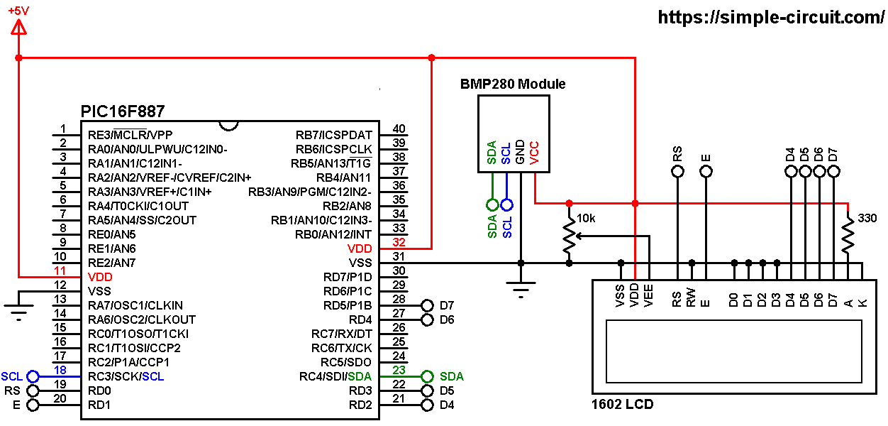
All the grounded terminals are connected together.
Generally, the BMP280 module has at least 4 pins because it can work in SPI mode or I2C mode. For the I2C mode we need 4 pins: VCC, GND, SCL and SDA where:
GND (ground) is connected to circuit ground (0V)
VCC is the supply pin, it is connected to +5V
SCL is I2C bus serial clock line, connected to PIC16F887 RC3 pin (#18)
SDA is I2C bus serial data line, connected to PIC16F887 RC4 pin (#23).
The 1602 LCD screen is used to display temperature and pressure values where:
RS —> pin RD0
E —> pin RD1
D4 —> pin RD2
D5 —> pin RD3
D6 —> pin RD4
D7 —> pin RD5
VSS, RW, D0, D1, D2, D3 and K are connected to circuit ground.
VEE to the variable resistor (or potentiometer) output
VDD to +5V and A to +5V through 330 ohm resistor.
VEE pin is used to control the contrast of the LCD. A (anode) and K (cathode) are the back light LED pins.
In this project the PIC16F887 microcontroller runs with its internal oscillator @ 8 MHz and MCLR pin is configured as an input pin.
Interfacing PIC16F887 with BMP280 sensor C code:
The C code below is for mikroC PRO for PIC compiler, it was tested with version 7.2.0.
To be able to compile project C code, a driver for the BMP280 sensor is required, download link is above. After you download driver file which named BMP280.c, add it to your project folder.
As any other I2C device, the BMP280 sensor has an I2C slave address which is 0xEC or 0xEE. This address depends on the connection of the SDO pin (used for SPI mode as serial data out or MISO), if the SDO pin is connected (directly or through resistor) to VCC (3.3V) the address will be 0xEE, and if it’s connected to GND the address will be 0xEC. The default I2C address of the library is defined as 0xEE and my device I2C address is 0xEC.
In the code the definition of the I2C slave address is as shown below:
1 2 | // define device I2C address: 0xEC or 0xEE (0xEE is library default address) #define BMP280_I2C_ADDRESS 0xEC |
The initialization of the BMP280 sensor is done using the function:
BMP280_begin(MODE_NORMAL, SAMPLING_X1, SAMPLING_X1, FILTER_OFF, STANDBY_0_5);
it returns 1 if OK and 0 if error. In the code the initialization of the sensor is as shown below:
1 2 3 4 5 6 7 8 | // initialize the BMP280 sensor according to the following settings: // BMP280_begin(mode, T_sampling, P_sampling, filter, standby_time) if(BMP280_begin(MODE_NORMAL, SAMPLING_X1, SAMPLING_X1, FILTER_OFF, STANDBY_0_5) == 0) { // connection error or device address wrong! lcd_out(1, 1, "Connection"); lcd_out(2, 1, "error!"); while(1); // stay here } |
The LCD displays “connection error!” if there was an error with the initialization of the device. Reading the values of temperature and pressure is done as shown below.
Note that the library returns the temperature in hundredths °C which means we’ve to divide it by 100 and it returns the pressure in Pa, to get the pressure in hPa we’ve to divide it by 100.
1 2 3 4 | // Read temperature (in hundredths C) and pressure (in Pa) // values from BMP280 sensor BMP280_readTemperature(&temperature); // read temperature BMP280_readPressure(&pressure); // read pressure |
Temperature and pressure values are displayed on the 16×2 LCD screen.
1 bar = 10000 Pa = 100 hPa.
( 1 hPa = 100 Pa) Pa: Pascal hPa: hectoPascal
Full mikroC code:
Configuration words:
CONFIG1 = 0x2CD4
CONFIG2 = 0x0700
1 2 3 4 5 6 7 8 9 10 11 12 13 14 15 16 17 18 19 20 21 22 23 24 25 26 27 28 29 30 31 32 33 34 35 36 37 38 39 40 41 42 43 44 45 46 47 48 49 50 51 52 53 54 55 56 57 58 59 60 61 62 63 64 65 66 67 68 69 70 71 72 73 74 75 76 77 78 79 80 | /************************************************************************************** Interfacing PIC16F887 with BMP280 temperature and pressure sensor. Temperature and pressure values are displayed on 16x2 LCD. C Code for mikroC PRO for PIC compiler. Internal oscillator used @ 8MHz Configuration words: CONFIG1 = 0x2CD4 CONFIG2 = 0x0700 This is a free software with NO WARRANTY. http://simple-circuit.com/ ***************************************************************************************/ // define device I2C address: 0xEC or 0xEE (0xEE is library default address) #define BMP280_I2C_ADDRESS 0xEC // LCD module connections sbit LCD_RS at RD0_bit; sbit LCD_EN at RD1_bit; sbit LCD_D4 at RD2_bit; sbit LCD_D5 at RD3_bit; sbit LCD_D6 at RD4_bit; sbit LCD_D7 at RD5_bit; sbit LCD_RS_Direction at TRISD0_bit; sbit LCD_EN_Direction at TRISD1_bit; sbit LCD_D4_Direction at TRISD2_bit; sbit LCD_D5_Direction at TRISD3_bit; sbit LCD_D6_Direction at TRISD4_bit; sbit LCD_D7_Direction at TRISD5_bit; // end LCD module connections #include <BMP280.c> // include BMP280 sensor driver source file long temperature; unsigned long pressure; char buffer[17]; // main function void main() { OSCCON = 0x70; // set internal oscillator to 8MHz I2C1_Init(400000); // initialize I2C communication delay_ms(1000); // wait a second Lcd_Init(); // initialize LCD module Lcd_Cmd(_LCD_CURSOR_OFF); // cursor off Lcd_Cmd(_LCD_CLEAR); // clear LCD // initialize the BMP280 sensor according to the following settings: // BMP280_begin(mode, T_sampling, P_sampling, filter, standby_time) if(BMP280_begin(MODE_NORMAL, SAMPLING_X1, SAMPLING_X1, FILTER_OFF, STANDBY_0_5) == 0) { // connection error or device address wrong! lcd_out(1, 1, "Connection"); lcd_out(2, 1, "error!"); while(1); // stay here } while(1) { // Read temperature (in hundredths C) and pressure (in Pa) // values from the BMP280 sensor BMP280_readTemperature(&temperature); // read temperature BMP280_readPressure(&pressure); // read pressure // print data on the LCD screen // 1: print temperature if(temperature < 0) sprinti(buffer, "Temp:-%02u.%02u%cC ", (unsigned int)(abs(temperature)/100), (unsigned int)(abs(temperature)%100), 223); else sprinti(buffer, "Temp: %02u.%02u%cC ", (unsigned int)(temperature/100), (unsigned int)(temperature%100), 223); lcd_out(1, 1, buffer); // 2: print pressure sprinti(buffer, "Pres: %04u.%02uhPa", (unsigned int)(pressure/100), (unsigned int)(pressure%100)); lcd_out(2, 1, buffer); delay_ms(2000); // wait 2 seconds } } // end of code. |
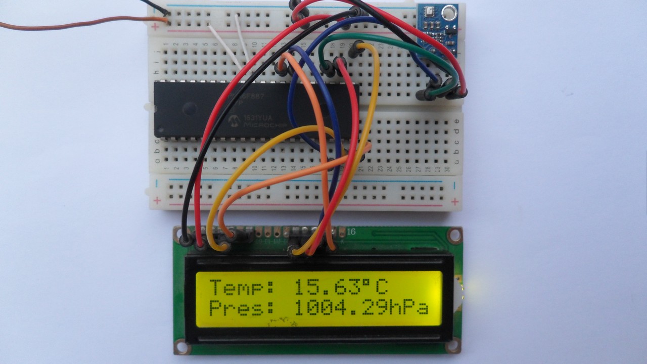
The Result:
Related Project:
PIC MCU with BME280 pressure, temperature and humidity sensor | mikroC Projects
Discover more from Simple Circuit
Subscribe to get the latest posts sent to your email.


