This topic shows how to build a simple DIY circuit that can measure AC current flowing to a load with nice accuracy compared to a well known digital multimeter instrument (FLUKE 289 true RMS multimeter).
This circuit can accurately measure electric current up to 50 Amps, it’s based on the Microchip PIC18F46K22 8-bit microcontroller and uses a current transformer with ratio 1000/1 to transform the high primary current that flows to the load into a low one which goes to the electronic circuit, the current transformer (CT) also isolates the high voltage power circuit from our low voltage electronic circuit.
Current values are printed on 1602 LCD screen.
CCS C Compiler is used in this project.
Hints:
No warranty is provided with this project, so do it at your own risk!
A part of project circuit may be subjected to a high voltage level which is very harmful to human body, so please be-careful!
Abbreviations:
AC: Alternating Current.
DC: Direct Current.
TRMS: True Root Mean Square.
ADC: Analog-to-Digital Converter
CT: Current Transformer
PCB: Printed Circuit Board
DIY: Do It Yourself
About Current Transformer:
Current transformer (CT) is an instrument transformer used to step down current by the inverse of its turns ratio. The secondary of the current transformer has more turns than the primary. Today, a standard CT secondary rated current is 5A or 1A, however, many CTs have smaller rated secondary current such as 20mA, 40mA …
Generally, current transformer is used to transmit current image information signal to a measuring instrument, protective device or similar apparatus.
Usually, the current transformer ratio is stated to include primary and secondary current ratings, for example 600:5, means that a 600A in the primary is converted into 5A in the secondary.
When current is passing through the primary of the CT, the secondary should be always kept shorted either through a shunt resistor (or meter coils) or through a shorting switch (for example a jumper) because the secondary may produce very high and harmful potential.
Another thing should be noted with CT is its rated apparent power, for example 10VA, or its maximum burden impedance.
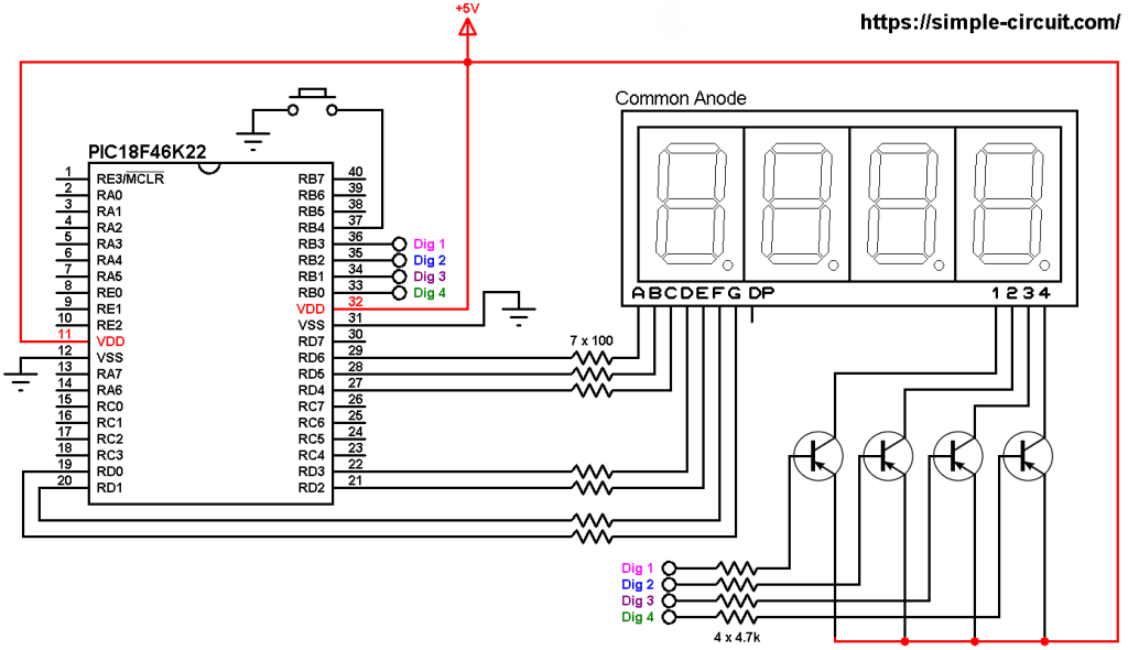
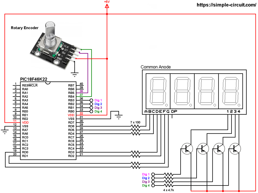
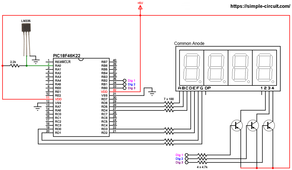
PIC18F46K22 MCU Based AC Current Measurement Project Circuit:
Project circuit diagram is shown below (click on the image for full resolution view).
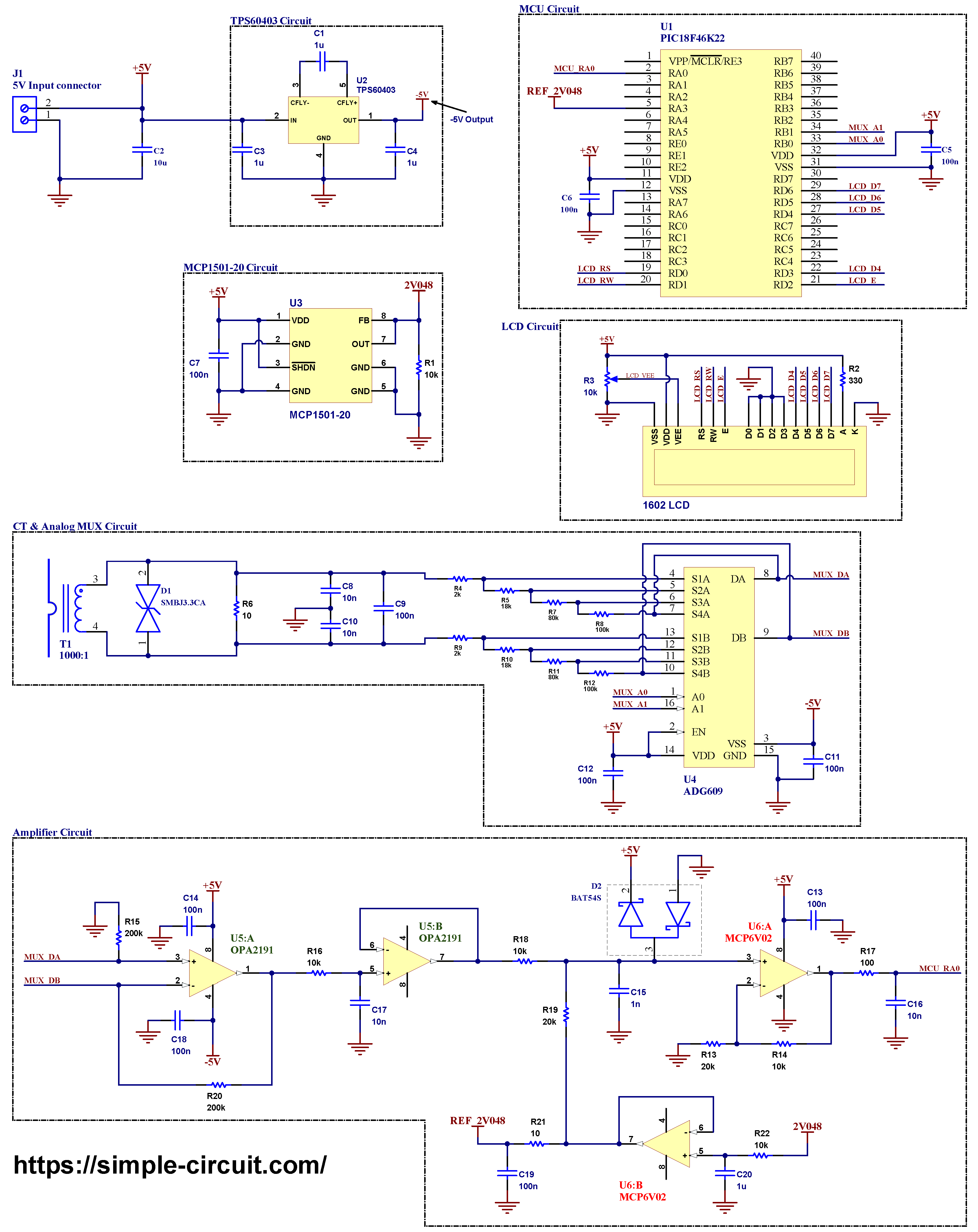
The main power source voltage of the circuit is 5V, it’s connected to connector J1 (5V Input connector) where pin 1 is negative (GND) and pin 2 is positive.
Hardware Required:
This is a summary of circuit required parts (circuit schematic diagram may contain some component parameters not mentioned below).
- PIC18F46K22 microcontroller (U1) —> datasheet
- Current transformer with turns ratio 1000:1 (T1)
- ADG609 analog multiplexer (U4) —> details
- OPA2191 op amp (U5) —> details
- MCP6V02 op amp (U6) —> details
- MCP1501-20 2.048 voltage reference (U3) —> details
- TPS60403 charge pump voltage inverter (U2) —> details
- 1602 LCD screen
- BAT54S dual serial small signal Schottky diode
- SMBJ3.3CA TVS diode
- 10uF capacitor (C2)
- 4 x 1uF capacitor (C1, C3, C4, C20)
- 10 x 100nF capacitor (C5, C6, C7, C9, C11, C12, C13, C14, C18, C19)
- 4 x 10nF capacitor (C8, C10, C16, C17)
- 1nF capacitor (C15)
- 2 x 200k ohm resistor (R15, R20)
- 2 x 100k ohm resistor (R8, R12)
- 2 x 80k ohm resistor (R7, R11)
- 2 x 20k ohm resistor (R13, R19)
- 2 x 18k ohm resistor (R5, R10)
- 5 x 10k ohm resistor (R1, R14, R16, R18, R22)
- 2 x 2k ohm resistor (R4, R9)
- 330 ohm resistor (R2)
- 100 ohm resistor (R17)
- 2 x 10 ohm resistor (R6, R21)
- 10k ohm variable resistor (R3)
- 5V source
- Breadboard & jumper wires…
- PIC MCU programmer (PICkit 3, PICkit 4 …)
Circuit description:
As shown in project circuit schematic diagram above, the current transformer which noted as T1 has a turns ratio of 1000/1, the secondary of the current transformer is connected to a shunt resistor with resistance of 10 Ohm (R6), this means at a load current of 50A AC the voltage generated across R6 will be: 50 x 10 / 1000 = 500 mV AC.
The SMBJ3.3CA bidirectional TVS diode is also connected in parallel with CT secondary and it is used to protect the electronic circuit from transient voltages.
Once the electric current is converter into voltage we can easily measure it using analog-to-digital converter module (ADC), in this circuit I’m using the PIC18F46K22 microcontroller which already has one ADC module with 10-bit resolution.
But before the signal goes to the MCU it firstly passes through a signal conditioning circuit which basically amplifies (if required), filters and adds a bias voltage of 1.024V in order for the ADC module to safely read the analog signal.
I used the ADG609 analog multiplexer from Analog Devices and OPA2191 op amp from Texas Instruments with some resistors to build a programmable gain amplifier with gains: 1, 2, 10 & 100 where we can change the gain through the ADG609 inputs A0 (pin #1) and A1 (pin #16). For example if A0 = A1 = LOW then the gain = 100, and so on.
The two chips ADG609 analog multiplexer and OPA2191 op amp are powered with bipolar supply of voltage ±5V, I used the TPS60403 60mA charge pump voltage inverter from Texas Instruments to get -5V where it automatically generates a -5 V from the +5 V supply.
Another alternatives with pin compatible to the ADG609 are: ADG409 –datasheet– and ADG5409 –datasheet-, the best one is the ADG5409 since its typical ON resistance is low (13.5 Ohm), but according to device’s datasheet the ADG409 as well as the ADG5409 requires a minimum dual voltage of ±9.
Resistor R7 has a resistance of not well used value -80k Ohm-, we may connect two resistors in parallel to get 80k, for example in my DIY circuit I used 120k in parallel with 240k.
Note that for better accuracy the following resistors should have a tolerance of 0.1%:
R4 ~ R15, R18, R19 & R20. A tolerance of 1% can also be used but it will directly affects the accuracy of the measurements.
The MCP1501-20 high-precision buffered voltage reference from Microchip is used to get a precise voltage of 2.048V which is then used as a positive voltage reference for the PIC18F46K22 microcontroller ADC module and a bias voltage for the AC signal.
The 1602 LCD screen (2 rows and 16 columns) is used to display the RMS value of the applied voltage, it is connected to the PIC18F46K22 MCU as follows:
RS —> pin RD0
RW —> pin RD1
E —> pin RD2
D4 —> pin RD3
D5 —> pin RD4
D6 —> pin RD5
D7 —> pin RD6
VSS, D0, D1, D2, D3 and K are connected to circuit ground
VEE to the variable resistor (or potentiometer) output
VDD to +5V and A to +5V through 330 ohm resistor.
VEE pin is used to control the contrast of the LCD. A (anode) and K (cathode) are the back light LED pins.
Internal oscillator of the PIC18F46K22 microcontroller is used @64MHz.
PIC18F46K22 MCU Based AC Ammeter Project C Code:
The C code below is for CCS C compiler, it was tested with version 5.112.
This C code calculates average and RMS values of AC signals, the average value is just used in the RMS calculations. The MCU only shows the RMS value of load current on the LCD and serial monitor.
Simply the average (mean or DC offset) value in discrete-time is the sum of all sample values divided by number of samples:

and the RMS value in discrete-time domain can be calculated using the following equation:

The PIC18F46K22 microcontroller contains a 10-bit ADC module, with a positive voltage reference of 2.048 V, a 0 V is digitally represented by 0 and a 2.048 V is represented by 1023.
Programming hints:
As we have a 10-bit ADC module working in the range [0, 2.048V], the MCU makes 64 samples every 1 cycle and saves the sampled data in an array named sample_array.
For a 50 Hz signal the period is 20 ms, the MCU takes one sample every 20000/64 = 312.5 us. I used CCP5 (Capture, Compare, PWM) module to start an ADC conversion every 312.5 us where the module is configured to use Timer5 for the compare operation, once the conversion is complete ADC interrupt saves the digital value in the variable sample_array. The array element is incremented every new reading until the filling of all elements and completion of the cycle.
At all times the microcontroller automatically changes the gain of the PGA circuit according to the load current, if the load current is less than 0.5A the MCU sets the gain to 100, if the load current is between 0.5A & 5A then the MCU sets the gain to 10, if the current is between 5A & 25A then the MCU sets the gain to 10 and if the load current is higher than 25A the MCU sets the gain to 1.
Full CCS C code:
1 2 3 4 5 6 7 8 9 10 11 12 13 14 15 16 17 18 19 20 21 22 23 24 25 26 27 28 29 30 31 32 33 34 35 36 37 38 39 40 41 42 43 44 45 46 47 48 49 50 51 52 53 54 55 56 57 58 59 60 61 62 63 64 65 66 67 68 69 70 71 72 73 74 75 76 77 78 79 80 81 82 83 84 85 86 87 88 89 90 91 92 93 94 95 96 97 98 99 100 101 102 103 104 105 106 107 108 109 110 111 112 113 114 115 116 117 118 119 120 121 122 123 124 125 126 127 128 129 130 131 132 133 134 135 136 137 138 139 140 141 142 143 144 145 146 147 148 149 150 151 152 153 154 155 156 157 158 159 160 161 162 163 164 165 166 167 168 169 170 171 | /********************************************************************** AC current measurement using PIC18F46K22 microcontroller. Electric current values are printed on 1602 LCD screen. C Code for CCS C compiler. This is a free software with NO WARRANTY - Use it at your own risk!. http://simple-circuit.com/ /**********************************************************************/ // LCD module connections #define LCD_RS_PIN PIN_D0 #define LCD_RW_PIN PIN_D1 #define LCD_ENABLE_PIN PIN_D2 #define LCD_DATA4 PIN_D3 #define LCD_DATA5 PIN_D4 #define LCD_DATA6 PIN_D5 #define LCD_DATA7 PIN_D6 // end LCD module connections // define programmable gain amplifier circuit control pins #define PGA1 PIN_B0 #define PGA2 PIN_B1 #include <18F46K22.h> #device ADC = 10 #fuses NOMCLR,NOLVP,NOBROWNOUT,PUT,NOXINST #use delay(internal = 64MHz) #include <stdint.h> #include <math.h> #include <lcd.c> // include LCD driver source file #byte CCPTMRS1 = getenv("SFR:CCPTMRS1") #byte CCP5CON = getenv("SFR:CCP5CON") #byte CCPR5L = getenv("SFR:CCPR5L") #byte CCPR5H = getenv("SFR:CCPR5H") const uint8_t n = 64; // number of samples int16_t sample_array[2][n]; // collected samples arrays uint16_t _offset = 0; // dc offset variable uint8_t m = 0, // sample number ( 0 <= m < n) dis = 0, // variable for data display on LCD gain; // variable for PGA s gain selection char current_str[6] = "00.00"; // electric current value string int1 sm = 0; // variable to distinguish between sample arrays ([1] or [2]) // one for collecting & saving samples and the other // for reading only, samples are selected alternatively const uint8_t gain_table[4] = {100, 10, 2, 1}; // programmable gain amplifier gain values // ADC ISR #INT_AD void ADC_ISR(void) { if (m < n) { sample_array[sm][m] = read_adc(ADC_READ_ONLY) ; _offset += sample_array[sm][m]; m++; // increment m for the next sample } } // gain set function void gain_set(uint8_t g) { switch(g) { case 0: output_low(PGA1); output_low(PGA2); break; case 1: output_high(PGA1); output_low(PGA2); break; case 2: output_low(PGA1); output_high(PGA2); break; case 3: output_high(PGA1); output_high(PGA2); } } // main function void main(void) { delay_ms(100); setup_adc(ADC_CLOCK_DIV_64); // set ADC module clock source to FOSC/64 = 1MHz // configure AN0 pin as analog input & set voltage references to: VSS - VREF (external voltage reference) setup_adc_ports(sAN0 | VSS_VREF); set_adc_channel(0); // select AN0 channel output_drive(PGA1); output_drive(PGA2); lcd_init(); // initialize LCD module lcd_putc("\fRMS Current:"); lcd_gotoxy(7, 2); lcd_putc("A"); enable_interrupts(GLOBAL); // enable global interrupts // CCP5 configuration: -compare mode, Special Event Trigger // -Timer is reset & ADON is set CCP5CON = 0x0B; CCPTMRS1 |= 0x08; // CCP5 – Capture/Compare modes use Timer5, PWM modes use Timer6 CCPR5H = 0x13; // set compare value, 5000 (0x1388) ==> 312.5 us @ FOSC/4 clk input CCPR5L = 0x88; // empty sample arrays for (uint8_t i = 0; i < n; i++) { sample_array[0][i] = 0; sample_array[1][i] = 0; } // set up Timer5 set_timer5(0); setup_timer_5(T5_INTERNAL); // Timer 5 clock source, FOSC/4 ==> 16MHz clear_interrupt(INT_AD); // clear ADC interrupt flag bit enable_interrupts(INT_AD); // enable ADC interrupt // gain initial configuration gain = 0; gain_set(gain); while (TRUE) { uint32_t ch_voltage = 0; // variable for MCU analog input channel applied // RMS voltage while (m < n) ; // wait for 1 cycle to complete (duration of 20 ms @ 50 Hz) sm = !sm; // toggle between reading and writing sample arrays m = 0; uint16_t c_offset = _offset / n; // save latest cycle offset value (dc offset)) _offset = 0; // calculate voltage RMS value for ( uint8_t i = 0; i < n; i++ ) { uint16_t j = abs( sample_array[!sm][i] - c_offset ); ch_voltage += ( (uint32_t)j * j ); } ch_voltage = ch_voltage / n; ch_voltage = sqrt(ch_voltage) * 100; // 100.0 to get a more precise value // (2 digits after the decimal point) // calculate real voltage RMS value applied to MCU analog channel (multiplied by 100) // 2 = 2048/1024 where 2048 is ADC +ive VREF = 2048 mV and 1024 is 10-bit ADC max digital value (aprroximately) // Note that this voltage is measured in milliVolts multiplied by 100 always ch_voltage = ch_voltage * 2 ; // calculate electric current passing through the CT, this result is also multiplied by 100 // 10 is resistance of the resistor connected through CT secondary uint16_t current = (ch_voltage / gain_table[gain]) / 10; // change gain if required if ( (current > 50 && gain == 0) || (current > 500 && gain == 1) || (current > 2500 && gain == 2) ) { gain++; gain_set(gain); } if ( (current < 2500 && gain == 3) || (current < 500 && gain == 2) || (current < 50 && gain == 1) ) { gain--; gain_set(gain); } dis++; // increment the display variable if ( dis > 24) { // display data on LCD every 500ms (25 x 20ms) dis = 0; sprintf( current_str, "%02u.%02u", (uint8_t)(current / 100), (uint8_t)(current % 100) ); lcd_gotoxy(1, 2); printf(lcd_putc, current_str); } } } // end of code. |
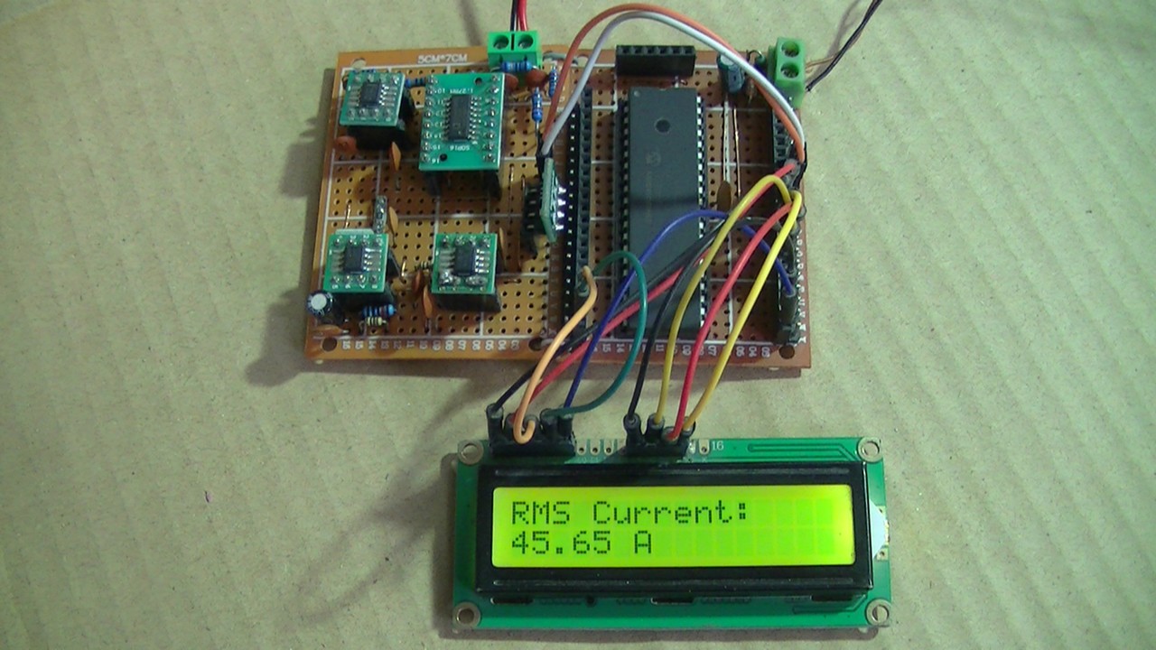
PIC18F46K22 MCU Based AC Ammeter Project Video:
The following small video shows my DIY circuit for this project, FLUKE 289 true RMS multimeter is used to test the accuracy of the circuit:
Related Project:
AC Voltage Measurement using PIC18F46K22 Microcontroller
Discover more from Simple Circuit
Subscribe to get the latest posts sent to your email.