This Arduino project demonstrates how to measure AC voltages of up to approximately 600 V using an Arduino UNO board and the AMC1301 differential input, differential output isolated amplifier.
With this circuit, it becomes possible to safely and accurately measure both phase-to-neutral (230 V) and phase-to-phase (400 V) voltages typically found in single- and three-phase electrical systems.
A 16×2 character LCD connected to the Arduino UNO board is used to continuously display the measured voltage readings in real time. The displayed data provides a clear and convenient indication of the AC voltage level, making the system suitable for educational, monitoring, and diagnostic applications. The LCD interface allows the user to observe voltage variations instantly, while the isolation amplifier ensures that the high-voltage measurement section remains electrically isolated from the low-voltage control circuitry, enhancing both safety and reliability.
Hints:
No warranty is provided with this project — proceed at your own risk!
Parts of the circuit may involve high voltages that are dangerous and potentially lethal to humans. Exercise extreme caution when building or testing this project.
Abbreviations:
AC: Alternating Current.
DC: Direct Current.
TRMS: True Root Mean Square.
ADC: Analog-to-Digital Converter
Voltage Measurement with Arduino and AMC1301 Isolated Amplifier Circuit:
Project circuit diagram is shown below.
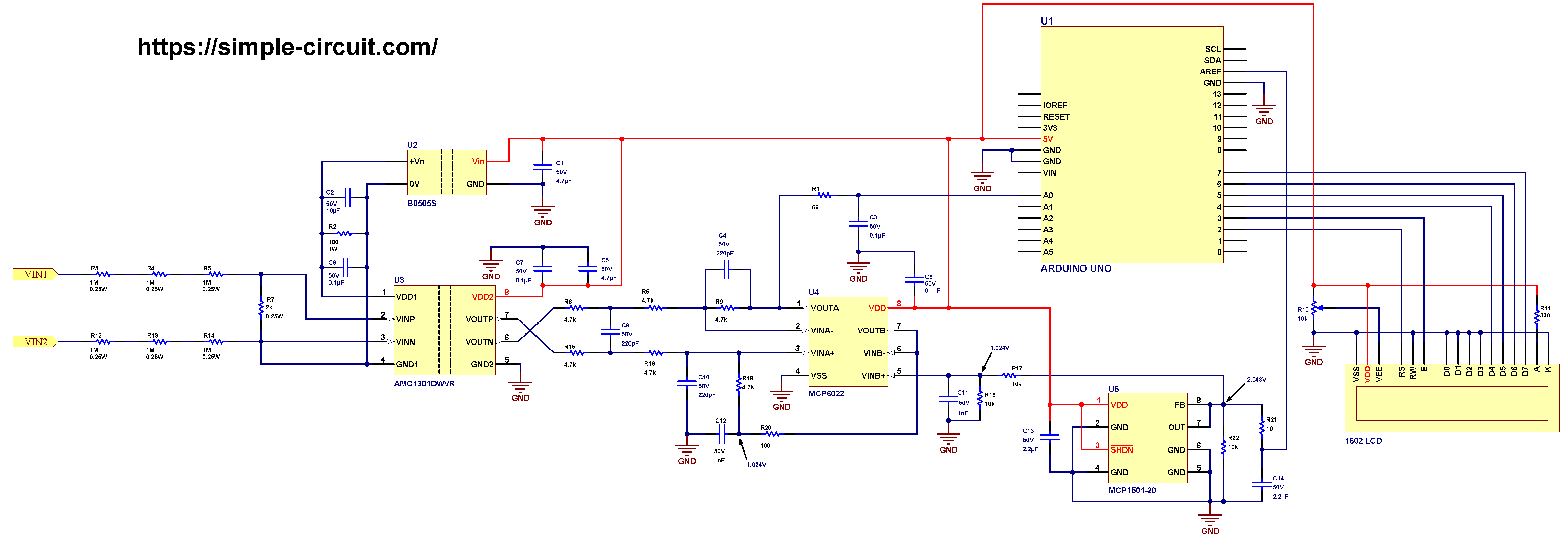
All grounded terminals must be externally connected together to ensure proper circuit operation and safety.
Hardware required:
The following is a summary of the components used in the circuit; some detailed parameters may appear only in the schematic diagram.
- Arduino Uno or equivalent board such as Arduino Nano
- AMC1301 isolated amplifier —> details
- MCP6022 op amp —> details
- MCP1501-20 2.048 voltage reference —> details
- B0505S isolated DC/DC converter (1 or 2-Watt)
- 1602 LCD screen
- 6 x 1M Ohm resistor (R3, R4, R5, R12, R13, R14)
- 3 x 10k Ohm resistor (R17, R19, R22)
- 6 x 4.7k Ohm resistor (R6, R8, R9, R15, R16, R18)
- 2k Ohm resistor (R7)
- 330 Ohm resistor (R11)
- 100 Ohm resistor (R2, R20)
- 68 Ohm resistor (R1)
- 10 Ohm resistor (R21)
- 10k Ohm variable resistor
- 10µF capacitor (C2)
- 2 x 4.7µF capacitor (C1, C5)
- 2 x 2.2µF capacitor (C13, C14)
- 4 x 0.1 capacitor (C3, C6, C7, C8)
- 2 x 1nF capacitor (C11, C12)
- 3 x 220pF capacitor (C4, C9, C10)
Circuit description:
Before connecting any high-voltage signal to the Arduino’s ADC input pin, it must first be scaled down, isolated, and filtered to ensure both safety and measurement accuracy.
The AC voltage to be measured is applied to the VIN1 and VIN2 terminals of the circuit. This input voltage is first attenuated using a precision voltage divider network composed of six 1 MΩ resistors (R3, R4, R5, R12, R13, R14) and one 2 kΩ resistor (R7).
The voltage divider is designed to reduce the input voltage to a maximum of ±250 mV, matching the input range of the AMC1301 isolation amplifier.
For example, an input of 400 V RMS is scaled down to approximately 120 mV RMS (±170 mV peak).
This allows the circuit to safely handle voltages up to about 600 V RMS (more precisely, ≈ 589 V RMS) without exceeding the amplifier’s input limits.
The AMC1301 from Texas Instruments is an isolated amplifier featuring a differential input and a differential output, separated by a high-performance isolation barrier.
Although primarily designed for current sensing applications, where its low input impedance is ideal for connection across a low-value shunt resistor, the AMC1301 can also be effectively used for voltage sensing.
When used in voltage measurement circuits, however, the amplifier’s internal input impedance must be carefully considered during circuit design to ensure accurate scaling and signal integrity.
The AMC1301 amplifier requires two separate power supplies — one for the high-side (input stage) and another for the low-side (output stage).
These two supplies must be galvanically isolated from each other; otherwise, the isolation feature of the amplifier becomes ineffective.
The AMC1301 has a fixed gain of 8.2 V/V and is designed to measure differential input signals of ±250 mV, providing an isolated differential output of ±2.05 V.
It features a common-mode output voltage (offset) of approximately 1.44 V and a bandwidth of 200 kHz.
In this project, as shown in the circuit schematic diagram above, the low-side of the AMC1301 is powered by the 5V supply from the Arduino Uno board, while the high-side is powered by an isolated 5V supply generated using the B0505S DC/DC converter.
The B0505S provides galvanic isolation between its input and output, allowing the circuit to safely create an isolated 5V rail from the Arduino’s 5V output. This ensures that the AMC1301 maintains proper isolation between the high-voltage measurement domain and the low-voltage control side.
The B0505S module is chosen for this project because it is widely available, low-cost, compact, and requires no external components for operation. It comes in a 4-pin package, with two pins for the input and two for the isolated output. In this project, either the B0505S-1W or B0505S-2W version can be used.
The voltage divider that scales the high input voltage down to a lower level is composed of resistors R3, R4, R5, R7, R12, R13, and R14, along with the AMC1301 input impedance (between VINP and VINN). The differential input impedance of the AMC1301 is approximately 18 kΩ, which appears in parallel with R7 (2 kΩ).
Therefore, the voltage divider gain can be calculated using the following equation:
Voltage-divider gain = (R7 // 18kΩ) / (R7 // 18kΩ + R3 + R4 + R5 + R12 + R13 + R14)
Voltage-divider gain = 1.8/6001.8
The differential output of the AMC1301 is fed into a differential amplifier circuit that filters the signal, applies a gain of 0.5 V/V, removes the AMC1301’s 1.44 V DC offset, and adds a new offset of 1.024 V.
The main active component of this stage is the Microchip MCP6022 dual operational amplifier, which is powered by the 5V supply from the Arduino board.
Since R9 = R18, R8 = R15, and R6 = R16, the gain of the differential amplifier stage is given by:
Gain = R18/(R16 + R15) = 4.7/(2 x 4.7) = 0.5
Hence, the overall circuit gain is the product of the voltage divider gain, the AMC1301 gain, and the MCP6022 differential amplifier gain:
Overall Gain = (1.8/6001.8) x 8.2 x 0.5 = 7.38/6001.8
This means that an input of 230 V RMS will appear at the Arduino analog input pin as:
230 x 7.38/6001.8 = 282.8mV AC
Thus, the AC signal at the Arduino analog input swings approximately between ±400 mV (±√2 × 282.8 mV).
After adding the 1.024 V DC offset, the resulting voltage swings between 1.424 V and 0.624 V.
Before the attenuated AC signal reaches the Arduino analog channel A0, it passes through an RC low-pass filter composed of R1 and C3.
The cutoff frequency of this filter can be calculated using the standard formula:
f = 1/(2 x π x R x C) = 23.4kHz
This filter helps remove high-frequency noise and ensures a stable analog reading by the Arduino’s ADC.
The 1.024 V DC offset is derived from a 2.048 V reference voltage divided by two using resistors R17 and R19.
The second operational amplifier of the MCP6022 is configured as a voltage follower (buffer) to provide a low-impedance voltage source. This prevents loading effects and ensures that the offset voltage remains stable regardless of other circuit components such as R18.
A precise 2.048 V reference voltage is generated using the Microchip MCP1501-20 precision voltage reference IC.
This reference voltage serves as the positive reference input (AREF) for the Arduino’s ADC module, ensuring accurate and consistent analog-to-digital conversion results.
The MCP1501-20 is powered from the 5V supply of the Arduino board, and its output is filtered before being connected to the AREF pin.
The 1602 LCD module (2 rows × 16 columns) is used to display the measured input voltage. It is connected to the Arduino board as follows:
RS —> Arduino digital pin 2
E —> Arduino digital pin 3
D4 —> Arduino digital pin 4
D5 —> Arduino digital pin 5
D6 —> Arduino digital pin 6
D7 —> Arduino digital pin 7
VSS, RW, D0, D1, D2, D3 and K are connected to GND,
VEE to the 10k Ohms variable resistor (or potentiometer) output,
VDD to Arduino 5V and A to Arduino 5V through 330 ohm resistor.
The VEE pin controls the display contrast, allowing adjustment via the potentiometer.
Pins A (anode) and K (cathode) power the LCD backlight LED, enabling visibility in low-light environments.
Voltage Measurement with Arduino and AMC1301 Isolated Amplifier Code:
The project code shown below was tested using both Arduino Uno and Arduino Nano boards.
Its primary function is to calculate the RMS (Root Mean Square) value of an AC signal applied to the analog input channel A0.
This implementation is designed specifically for AC voltage measurement.
When a DC voltage is applied to the input terminals, the display will show 0 Volts, because the code continuously removes (subtracts) the average or DC component from the input signal before performing RMS computation.
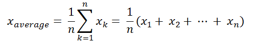
In discrete-time processing, the average (mean or DC offset) value of a signal is obtained by summing all sampled values and dividing by the total number of samples:
The RMS (Root Mean Square) value in discrete-time form can be calculated using the equation below. This formula effectively removes the DC component from the signal and computes the true AC RMS value, providing an accurate measurement of the signal’s effective voltage level.

The Arduino uno board microcontroller (ATmega328P) has a 10-bit ADC module, the positive voltage reference is 2.048V means that a 2.048V is digitally represented by 1023 and 0V is represented by 0 (1 digit for every 2mV).
The Arduino Uno board is based on the ATmega328P microcontroller, which features a 10-bit Analog-to-Digital Converter (ADC).
In this project, the ADC’s positive voltage reference is set to 2.048 V, meaning that the full-scale input voltage (2.048 V) corresponds to a digital value of 1023, while 0 V corresponds to 0.
Therefore, each ADC count (or step) represents approximately 2 mV per bit:
ADC Resolution = 2.048 V/1023 ≈ 2.00 mV/bit
This high precision allows accurate measurement of the conditioned analog signal, ensuring that even small voltage variations resulting from the scaled-down AC input can be precisely detected by the Arduino.
1 2 3 4 5 6 7 8 9 10 11 12 13 14 15 16 17 18 19 20 21 22 23 24 25 26 27 28 29 30 31 32 33 34 35 36 37 38 39 40 41 42 43 44 45 46 47 48 49 50 51 52 53 54 55 56 57 58 59 60 61 62 63 64 65 66 67 68 69 70 71 72 73 74 75 | / /************************************************************************ * * AC Voltage measurement with Arduino. * Voltage values are printed on 1602 LCD screen. * This is a free software with NO WARRANTY - Use it at your own risk! * http://simple-circuit.com/ * ************************************************************************/ #include <LiquidCrystal.h> // include Arduino LCD library // LCD module connections (RS, E, D4, D5, D6, D7) LiquidCrystal lcd(2, 3, 4, 5, 6, 7); // define analog channel input #define INPUT_CHANNEL A0 void setup(void) { delay(1000); lcd.begin(16, 2); // set up the LCD's number of columns and rows lcd.setCursor(0, 0); // move cursor to column 0, row 0 [position (0, 0)] lcd.print("RMS Voltage ="); analogReference(EXTERNAL); // set positive reference voltage to external } const uint16_t n = 512; // total number of samples (readings) int16_t r_array[n]; // readings array float average, rms; void loop() { average = 0; rms = 0; // read voltage at INPUT_CHANNEL 'n' times and save data to 'r_array' for (uint16_t i = 0; i < n; i++) { r_array[i] = analogRead(INPUT_CHANNEL); delayMicroseconds(200); } // calculate signal average (DC offset) for (uint16_t i = 0; i < n; i++) average += r_array[i]; average = average / n; // calculate AC signal RMS value for (uint16_t i = 0; i < n; i++) { if( abs(r_array[i] - average) > 3) rms += sq( r_array[i] - average ); } // calculate Arduino analog channel input RMS voltage in millivolts rms = 2 * sqrt(rms/n); // 2 = 2048/1024 // now calculate actual RMS input voltage (6001.8/7.83 is inverse of whole circuit gain) rms = rms * 6001.8 / 7.38; char _buffer[8]; lcd.setCursor(0, 1); if(rms >= 100000.0) // if voltage >= 100000.0 mV = 100.0 V sprintf( _buffer, "%3u.%1u V", (uint16_t)(rms/1000), (uint16_t)(rms/100) % 10 ); else if (rms >= 10000.0) // if voltage >= 10000.0 mV = 10.0 V sprintf( _buffer, " %2u.%1u V", (uint8_t)rms/1000, (uint16_t)(rms/100) % 10 ); else // if voltage < 10 V sprintf( _buffer, " %1u.%1u V", (uint8_t)(rms/1000), (uint8_t)(rms/100) % 10 ); lcd.print(_buffer); delay(1000); } // end of code. |
Voltage Measurement with Arduino and AMC1301 Isolated Amplifier – Demonstration Video:
The following short video demonstrates the hardware circuit in operation, measuring a 230V AC (phase-to-neutral) mains voltage.
It showcases the performance of the AMC1301 isolated amplifier and Arduino-based measurement system, confirming accurate and stable voltage readings under real operating conditions.
Discover more from Simple Circuit
Subscribe to get the latest posts sent to your email.


Hello, firstly thank you for your work. Please can you provide us the simulation of this assembly please ? Which software have you used please ?
Thank you in advance !
You are a master in embedded programming, thank you for providing a very large scale tutorial platform
dear please make a USB mic using Arduino or pic16f887.
Welcome back after more than a year (last post March 10 2020). Hope you and yours are doing well. Thank you for your hard works on continuing to post tutorials, they are very educational.
Thanks for your support!
very nice tutorial can you do a project on ac current measurement using current readily available sensor in the market thanks