This is another example that shows how to interface PIC16F887 microcontroller with common anode 7-segment display.
This example shows how to print rotary encoder values (positive or negative) on 4-digit 7-segment display where the first digit (most left) is used for the minus sign ( -). Here the rotary encoder is an input device and the 7-segment display is an output device.
The compiler used in this example is mikroC PRO for PIC.
To see how to interface PIC16F887 with 7-segment display (digital counter example), visit the following post:
Interfacing PIC microcontroller with 7-segment display | mikroC Projects
And to see how the rotary encoder works and how to interface it with PIC16F887 in order to control a DC motor speed, take a look at this project:
DC Motor control with rotary encoder and PIC MCU | mikroC Projects
Components Required:
- PIC16F887 microcontroller —-> datasheet
- 4-digit common anode 7-segment display
- 4 x PNP transistor (2SA1015, 2S9015, 2N3906 …)
- Rotary encoder
- 7 x 100 ohm resistor
- 4 x 4.7k ohm resistor
- 5V source
- Breadboard
- Jumper wires
- PIC MCU Programmer (PICkit 3, PICkit 4…)
PIC16F887 with 7-segment display and rotary encoder circuit:
The image below shows our example circuit diagram.
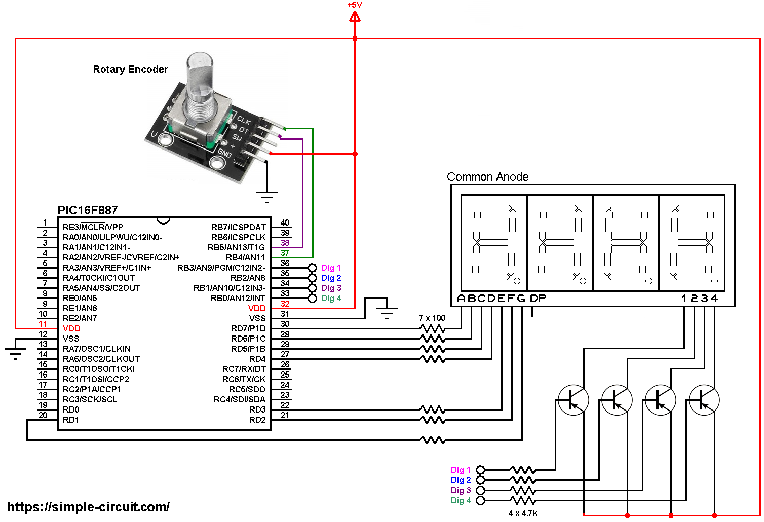
All the grounded terminals are connected together.
The rotary encoder board has 5 pins: GND, + , SW, DT (pin B or data pin) and CLK (pin A or clock pin) where:
GND is connected to circuit ground (0V)
+ is connected to +5V
SW is push button pin, not used in this example
DT is connected to PIC16F887 pin RB5 (#38)
CLK is connected to PIC16F887 pin RB4 (#37)
The 4 transistors are of the same type (PNP).
The PIC16F887 microcontroller uses its internal oscillator @ 8 MHz, MCLR pin is configured as an input pin.
PIC16F887 with 7-segment display and rotary encoder C code:
The following C code is for mikroC PRO for PIC compiler, it was tested with version 7.2.0.
Since the 4 digits are multiplexed we need to refresh the display very quickly (display one digit at a time, others are off), for that I used Timer0 module (8-bit timer) interrupt with 1:16 prescaler, this means Timer0 overflows every 2048 microseconds { 256/[8/(4 x 16)] = 256 x 8 = 2048 microseconds }.
PORTB interrupt-on-change is enabled for pins RB4 and RB5 which are respectively connected to CLK and DT pins of the rotary encoder. This interrupt detects falling and rising of the two lines:
1 2 | INTCON = 0xE8; // enable global, peripheral, PORTB change & Timer0 overflow interrupts IOCB = 0x30; // enable RB4 & RB5 pin change interrupt |
Full mikroC code:
Configuration words:
CONFIG1 = 0x2CD4
CONFIG2 = 0x0700
1 2 3 4 5 6 7 8 9 10 11 12 13 14 15 16 17 18 19 20 21 22 23 24 25 26 27 28 29 30 31 32 33 34 35 36 37 38 39 40 41 42 43 44 45 46 47 48 49 50 51 52 53 54 55 56 57 58 59 60 61 62 63 64 65 66 67 68 69 70 71 72 73 74 75 76 77 78 79 80 81 82 83 84 85 86 87 88 89 90 91 92 93 94 95 96 97 98 99 100 101 102 103 104 105 106 107 108 109 110 111 112 113 114 115 116 117 118 119 120 121 122 123 124 125 126 127 128 129 130 131 132 133 134 135 136 137 138 139 140 141 142 143 144 145 146 147 | /************************************************************************************** Interfacing PIC16F887 with common anode 7-segment display. Print rotary encoder values on 4-digit 7-segment display. C Code for mikroC PRO for PIC compiler. Internal oscillator used @ 8MHz Configuration words: CONFIG1 = 0x2CD4 CONFIG2 = 0x0700 This is a free software with NO WARRANTY. http://simple-circuit.com/ ***************************************************************************************/ unsigned short current_digit, last_read; short quad = 0, change; int enc_value = 0; void disp(unsigned short number) { switch (number) { case 0: // print 0 PORTD = 0x02; break; case 1: // print 1 PORTD = 0x9E; break; case 2: // print 2 PORTD = 0x24; break; case 3: // print 3 PORTD = 0x0C; break; case 4: // print 4 PORTD = 0x98; break; case 5: // print 5 PORTD = 0x48; break; case 6: // print 6 PORTD = 0x40; break; case 7: // print 7 PORTD = 0x1E; break; case 8: // print 8 PORTD = 0x00; break; case 9: // print 9 PORTD = 0x08; break; case 10: // print - PORTD = 0xFC; } } void interrupt() { if(T0IF_bit) // Timer0 overflow ISR { unsigned int abs_value = abs(enc_value); // abs: absolute value PORTD = 0xFE; // turn off all segments if(current_digit == 1) { PORTB = 0x07; // turn on digit 1 (most left) if(enc_value < 0) // if negative value { // print minus sign (-) on digit 1 (most left digit) disp(10); // prepare to display digit 1 } } if(current_digit == 2) { PORTB = 0x0B; // turn on digit 2 disp((abs_value / 100) % 10); } if(current_digit == 3) { PORTB = 0x0D; // turn on digit 3 disp((abs_value / 10) % 10); } if(current_digit == 4) { PORTB = 0x0E; // turn on digit 4 (most right) disp(abs_value % 10); } current_digit = (current_digit % 4) + 1; T0IF_bit = 0; // clear Timer0 interrupt flag bit } if (RBIF_bit && (PORTB.F4 || !PORTB.F4)) // PORTB change ISR { short encoderRead; encoderRead = PORTB & 0x30; if(encoderRead == last_read) return; if(encoderRead.F4 == last_read.F5) quad -= 1; else quad += 1; last_read = encoderRead; RBIF_bit = 0; // clear pin change interrupt flag bit } } short EncoderGet(void) { short val = 0; while(quad >= 4) { val += 1; quad -= 4; } while(quad <= -4) { val -= 1; quad += 4; } return val; } // main function void main() { OSCCON = 0x70; // set internal oscillator to 8MHz ANSELH = 0; // configure all PORTB pins as digital PORTB = 0; TRISB = 0xF0; // configure RB0, RB1, RB2 & RB3 as outputs PORTD = 0; TRISD = 0; TMR0 = 0; // reset Timer0 OPTION_REG = 0x83; // set Timer0 prescaler to 1:16 INTCON = 0xE8; // enable global, peripheral, PORTB change & Timer0 overflow interrupts IOCB = 0x30; // enable RB4 & RB5 pin change interrupt last_read = PORTB & 0x30; while(1) { change = EncoderGet(); if(change) enc_value += change; delay_ms(100); // wait 100 milliseconds } } // end of code. |
My hardware circuit gave me a result similar to what’s shown in the following video where Arduino UNO is used instead of the PIC16F887 microcontroller:
Discover more from Simple Circuit
Subscribe to get the latest posts sent to your email.


