This post shows how to control DC motor speed and direction of rotation using PIC16F887 microcontroller, rotary encoder and L293D motor driver chip.
The compiler used in this project is mikroElektronika mikroC PRO for PIC.
Last time I made a simple controller circuit that controls speed and direction of rotation of DC motor, project link is below:
DC Motor control with PIC microcontroller | mikroC Projects
In this example I used the rotary encoder shown in the following image:
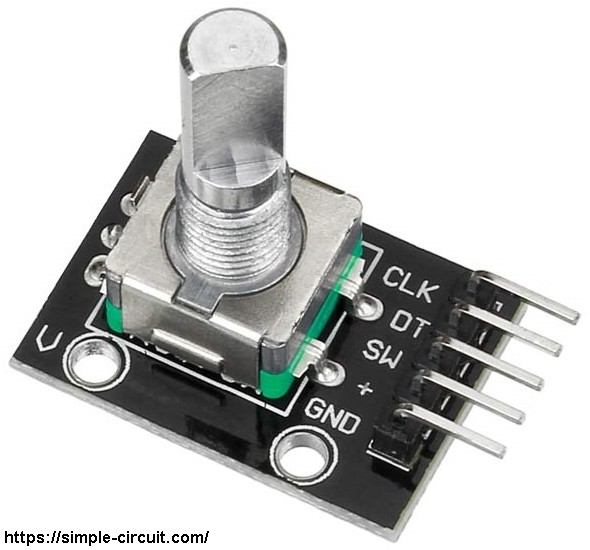
The rotary encoder has 5 pins: GND, + (+5V or 3.3V), SW (push button), DT (pin B) and CLK (pin A).
As an addition to the rotary encoder there is a push button and three pull up resistors for pins SW, DT and CLK of 10k ohm each. With the three pull-up resistors, the normal state of each terminal is logic high.
The rotary encoder generates (when rotating) two square waves on pins A (CLK) and B (DT) with 90° out of phase as shown in the figure below:
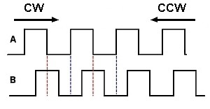
As shown in the figure, the rotary encoder has 4 phases:
phase 1: A = 0, B = 0
phase 2: A = 1, B = 0
phase 3: A = 1, B = 1
phase 4: A = 0, B = 1
Hardware Required:
- PIC16F887 microcontroller —-> datasheet
- L293D driver —-> datasheet
- Rotary encoder
- 12V DC motor
- Breadboard
- 12V source
- 5V source
- Jumper wires
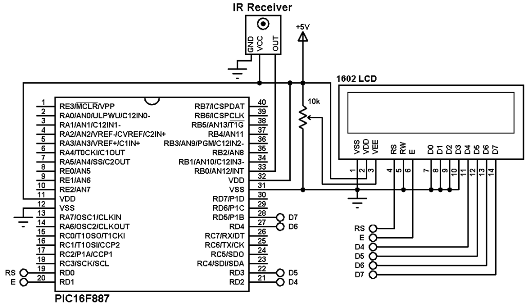
DC Motor control with rotary encoder and PIC16F887 circuit:
Project circuit schematic diagram is shown in the following image.
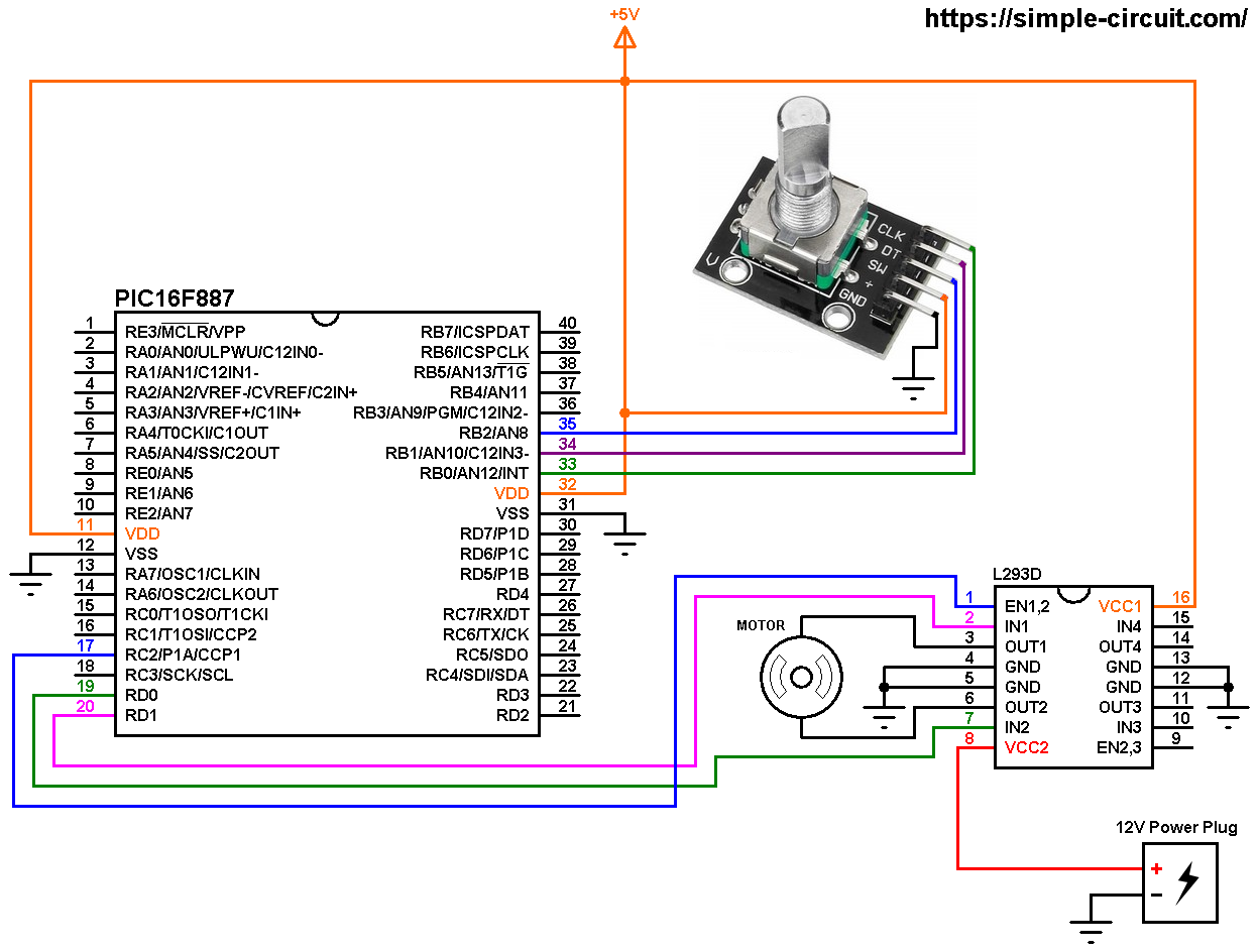
(All grounded terminals are connected together)
The circuit is supplied with two power sources, one with voltage of 5V which supplies the PIC16F887 microcontroller, the rotary encoder board and the L293D driver IC (VCC1), and the second source with voltage of 12V which supplies the L293D chip (VCC2) (therefore the DC motor). The DC motor nominal voltage is 12V.
The L293D driver has 2 VCCs: VCC1 is +5V and VCC2 is +12V (same as motor nominal voltage). IN1 and IN2 are the control pins where:
| IN1 | IN2 | Function |
| L | H | Direction 1 |
| H | L | Direction 2 |
| L | L | Fast motor stop |
| H | H | Fast motor stop |
The PIC16F887 generates a PWM signal on pin RC2 (#17) using CCP1 module (CCP: Capture/Compare/PWM), this pin is connected to EN1,2 pin of the L293D chip. IN1 and IN2 pins are connected to RD0 and RD1 respectively (they can be reversed).
The rotary encoder push button terminal is connected to pin RB2, with this button we can change the direction of rotation of the motor. CLK and DT pins are connected to RB0 and RB1 respectively.
In this project the PIC16F887 microcontroller uses its internal oscillator @ 8 MHz, MCLR pin is configured as an input pin.
DC Motor control with rotary encoder and PIC16F887 C code:
The following C code is for mikroC PRO for PIC compiler, it was tested with version 7.2.0.
Rotary encoder pushbutton (connected to RB2) and the control lines (connected to RD0 and RD1) are defined in the code as shown below:
1 2 3 4 5 6 | // define rotary encoder button pin connection #define SW RB2_bit // define motor control pins #define IN1 RD1_bit #define IN2 RD0_bit |
Internal weak pull-up is enabled for pin RB2, the following lines are used for that:
1 2 3 | // enable RB1 internal pull up NOT_RBPU_bit = 0; // clear RBPU bit (OPTION_REG.7) WPUB = 0x04; // WPUB register = 0b00000100 |
PORTB interrupt-on-change is enabled for pins RB0 and RB1 which are respectively connected to CLK and DT pins of the rotary encoder. This interrupt detects falling and rising of the two lines:
1 2 | INTCON = 0xC8; // enable global, peripheral and PORTB change interrupts IOCB = 0x03; // enable RB0 & RB1 pin change interrupt |
Full mikroC code:
Configuration words:
CONFIG1 = 0x2CD4
CONFIG2 = 0x0700
1 2 3 4 5 6 7 8 9 10 11 12 13 14 15 16 17 18 19 20 21 22 23 24 25 26 27 28 29 30 31 32 33 34 35 36 37 38 39 40 41 42 43 44 45 46 47 48 49 50 51 52 53 54 55 56 57 58 59 60 61 62 63 64 65 66 67 68 69 70 71 72 73 74 75 76 77 78 79 80 81 82 83 84 85 86 87 88 89 90 91 92 93 94 95 96 97 98 99 100 101 102 103 104 105 106 107 108 109 110 111 112 113 114 115 116 117 118 119 120 121 122 123 124 125 126 127 128 129 130 131 132 133 | /************************************************************************************** DC Motor control with PIC16F887 MCU and rotary encoder. C Code for mikroC PRO for PIC compiler Internal oscillator used @ 8MHz Configuration words: CONFIG1 = 0x2CD4 CONFIG2 = 0x0700 This is a free software with NO WARRANTY. http://simple-circuit.com/ ***************************************************************************************/ // define rotary encoder button pin connection #define SW RB2_bit // define motor control pins #define IN1 RD1_bit #define IN2 RD0_bit bit direction; char last_read; short quad = 0, change; int motor_speed = 0; void Interrupt() { if (RBIF_bit && (PORTB.F0 || !PORTB.F0)) // PORTB change ISR { short encoderRead; RBIF_bit = 0; // clear pin change interrupt flag bit encoderRead = PORTB & 0x03; if(encoderRead == last_read) return; if(encoderRead.F0 == last_read.F1) quad -= 1; else quad += 1; last_read = encoderRead; } } // a small function for button debounce char debounce () { char i, count = 0; for(i = 0; i < 5; i++) { if (SW == 0) count++; delay_ms(10); } if(count > 2) return 1; else return 0; } short EncoderGet(void) { short value = 0; while(quad >= 4){ value += 1; quad -= 4; } while(quad <= -4){ value -= 1; quad += 4; } return value; } // main function void main() { OSCCON = 0x70; // set internal oscillator to 8MHz ANSELH = 0; // configure all PORTB pins as digital PORTD = 0; // PORTD initial state TRISD = 0; // configure all PORTD pins as outputs // enable RB2 internal pull up NOT_RBPU_bit = 0; // clear RBPU bit (OPTION_REG.7) WPUB = 0x04; // WPUB register = 0b00000100 delay_ms(500); // wait 1/2 second INTCON = 0xC8; // enable global, peripheral and PORTB change interrupts IOCB = 0x03; // enable RB0 & RB1 pin change interrupt last_read = PORTB & 0x03; PWM1_Init(1000); // initialize PWM1 with frequency of 1KHz PWM1_Start(); // start PWM1 direction = 0; while(1) { if(!SW) // if Button is pressed if(debounce()) // call debounce function { direction = ~direction; // invert direction variable switch (direction) { case 0: IN1 = 1; IN2 = 0; break; case 1: IN1 = 0; IN2 = 1; } while(debounce()); // call debounce function (wait for Button to be released) } change = EncoderGet(); if(change) { motor_speed += change; if(motor_speed > 255) motor_speed = 255; if(motor_speed < 0) motor_speed = 0; // set PWM1 duty cycle PWM1_Set_Duty(motor_speed); } delay_ms(50); // wait 50 ms } } // end of code. |
The following video shows a similar hardware circuit where PIC16F877A microcontroller is used:
Discover more from Simple Circuit
Subscribe to get the latest posts sent to your email.