This post shows how to control DC motor speed and direction of rotation using PIC16F887 microcontroller and L293D motor driver.
The L293D quadruple half-H drivers chip allows us to drive 2 motors in both directions. With one PWM signal from the PIC16F887 and two control signals we can easily control the speed as well as the direction of rotation of one DC motor. PWM: Pulse Width Modulation.
The compiler used in this project is mikroElektronika mikroC PRO for PIC.
In this project the speed of the DC motor is controlled using a potentiometer connected to the PIC16F887 microcontroller. The speed is related to the variation of the duty cycle of the PWM signal, the DC motor reaches its maximum speed when the duty cycle is equal to 100% (255 for 8-bit resolution).
The direction of rotation is controlled using a pushbutton, if the pushbutton is pressed the motor will change its direction.
Components Required:
- PIC16F887 microcontroller —-> datasheet
- L293D driver —-> datasheet
- 12V DC motor
- 10k ohm potentiometer
- Push button
- 5V source
- 12V source
- Breadboard
- Jumper wires
DC Motor control with PIC16F887 microcontroller circuit:
The following image shows the circuit schematic diagram of this example.
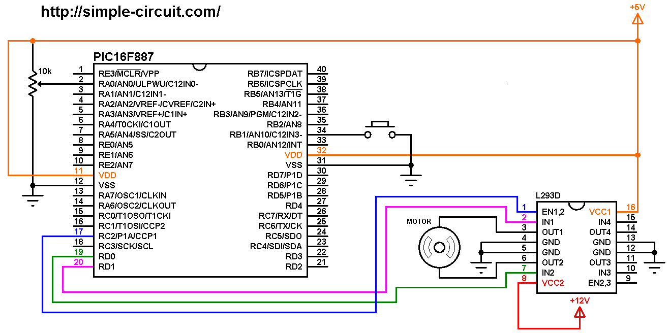
(All grounded terminals are connected together)
The circuit is supplied with two power sources, one with voltage of 5V which supplies the PIC16F887 microcontroller and the L293D driver IC (VCC1), and the second source with voltage of 12V which supplies the L293D chip (VCC2) (therefore the DC motor). The DC motor nominal voltage is 12V.
The speed of the DC motor (both directions) is controlled with the 10k potentiometer which is connected to AN0 pin of the PIC16F887 (#2) and the direction of rotation is controlled with the push button which is connected to RB1 pin (#34). If the button is pressed the motor will change its direction of rotation directly.
The L293D driver has 2 VCCs: VCC1 is +5V and VCC2 is +12V (same as motor nominal voltage). IN1 and IN2 are the control pins where:
| IN1 | IN2 | Function |
| L | H | Direction 1 |
| H | L | Direction 2 |
| L | L | Fast motor stop |
| H | H | Fast motor stop |
The PIC16F887 generates a PWM signal on pin RC2 (#17) using CCP1 module (CCP: Capture/Compare/PWM), this pin is connected to EN1,2 pin of the L293D chip. IN1 and IN2 pins are connected to RD0 and RD1 respectively (they can be reversed).
In this project the PIC16F887 microcontroller uses its internal oscillator @ 8 MHz, MCLR pin is configured as an input pin.
DC Motor control with PIC16F887 microcontroller C code:
The following C code is for mikroC PRO for PIC compiler, it was tested with version 7.2.0.
The pushbutton (connected to RB1) and the control lines (connected to RD0 and RD1) are defined in the code as shown below:
1 2 3 4 5 | // direction button connected to pin RB1 #define Button RB1_bit // define motor control pins #define IN1 RD1_bit #define IN2 RD0_bit |
Internal weak pull-up is enabled for pin RB1, the following lines are used for that:
1 2 3 | // enable RB1 internal pull up NOT_RBPU_bit = 0; // clear RBPU bit (OPTION_REG.7) WPUB = 0x02; // WPUB register = 0b00000010 |
The resolution of the ADC module is 10-bit which means its output digital value can vary between 0 and 1023. If the analog input voltage is 0 the digital value is also 0, and if the analog voltage is 5V (VDD) the digital value is 1023.
MikroC PRO for PIC compiler has a built-in library for PWM. With this library the resolution of the PWM is 8-bit which means the duty cycle can be between 0 and 255.
In this project I used the ADC digital value to set the PWM signal duty cycle, and to convert a 10-bit number to 8-bit, we’ve shift it (the 10-bit number) to the right by 2 as shown below (motor_speed >> 2):
1 2 | // set PWM1 duty cycle PWM1_Set_Duty(motor_speed >> 2); |
Full mikroC code:
Configuration words:
CONFIG1 = 0x2CD4
CONFIG2 = 0x0700
1 2 3 4 5 6 7 8 9 10 11 12 13 14 15 16 17 18 19 20 21 22 23 24 25 26 27 28 29 30 31 32 33 34 35 36 37 38 39 40 41 42 43 44 45 46 47 48 49 50 51 52 53 54 55 56 57 58 59 60 61 62 63 64 65 66 67 68 69 70 71 72 73 74 75 76 77 78 79 80 81 82 83 84 | /************************************************************************************** DC Motor speed and direction of rotation control with PIC16F887 MCU. C Code for mikroC PRO for PIC compiler Internal oscillator used @ 8MHz Configuration words: CONFIG1 = 0x2CD4 CONFIG2 = 0x0700 This is a free software with NO WARRANTY. http://simple-circuit.com/ ***************************************************************************************/ // direction button connected to pin RB1 #define Button RB1_bit // define motor control pins #define IN1 RD1_bit #define IN2 RD0_bit bit direction; unsigned int motor_speed; // a small function for Button debounce char debounce () { char i, count = 0; for(i = 0; i < 5; i++) { if (Button == 0) count++; delay_ms(10); } if(count > 2) return 1; else return 0; } // main function void main() { OSCCON = 0x70; // set internal oscillator to 8MHz ANSELH = 0; // configure all PORTB pins as digital PORTD = 0; // PORTD initial state TRISD = 0; // configure all PORTD pins as outputs // enable RB1 internal pull up NOT_RBPU_bit = 0; // clear RBPU bit (OPTION_REG.7) WPUB = 0x02; // WPUB register = 0b00000010 ADC_Init(); // initialize ADC module PWM1_Init(1000); // initialize PWM1 with frequency of 1KHz PWM1_Start(); // start PWM1 delay_ms(1000); // wait 1 second direction = 0; while(1) { if(!Button) // if Button is pressed if(debounce()) // call debounce function { direction = ~direction; // invert direction variable switch (direction) { case 0: IN1 = 1; IN2 = 0; break; case 1: IN1 = 0; IN2 = 1; } while(debounce()); // call debounce function (wait for Button to be released) } // read analog data from channel 0 and store it in 'motor_speed' motor_speed = ADC_Read(0); // set PWM1 duty cycle PWM1_Set_Duty(motor_speed >> 2); delay_ms(50); // wait 50 ms } } // end of code. |
The following small video shows Proteus simulation of the project:
and this video shows how the project should work in hardware circuit where Arduino UNO board is used instead of the PIC16F887 microcontroller:
Related Projects:
DC Motor control with rotary encoder and PIC MCU | mikroC Projects
Discover more from Simple Circuit
Subscribe to get the latest posts sent to your email.