This project shows how to interface ESP8266 NodeMCU board with ST7789 SPI TFT display and DHT22 (AM2302 – RHT03) digital humidity & temperature sensor.
The values of temperature and relative humidity are printed on the ST7789 TFT display respectively in °C and rH%.
The ST7789 TFT module contains a display controller with the same name: ST7789. It’s a color display that uses SPI interface protocol and requires 3, 4 or 5 control pins, it’s low cost and easy to use. This display is an IPS display, it comes in different sizes (1.3″, 1.54″ …) but all of them should have the same resolution of 240×240 pixel, this means it has 57600 pixels. This module works with 3.3V only and it does not support 5V.
TFT: Thin-Film Transistor.
SPI: Serial Peripheral Interface.
IPS: In-Plane Switching.
To see how to interface the NodeMCU board with ST7789 TFT display, visit this post:
Interfacing ESP8266 NodeMCU with ST7789 TFT Display
About DHT2 sensor:
This sensor has the following characteristics:
- Humidity Range: 0 ~ 100% RH
- Humidity Accuracy: ±2% RH (max ±5% RH)
- Temperature Range: -40 ~ 80 °C
- Temperature Accuracy: ±0.5 °C
- Operating Voltage: 3.3V ~ 5.5V
- Resolution = 0.1
Hardware Required:
- ESP8266 NodeMCU board
- ST7789 TFT display module
- DHT22 (AM2302, RHT03) humidity and temperature sensor —-> datasheet
- 4.7k ohm resistor
- Micro USB cable (for programming and powering the whole circuit)
- Breadboard
- Jumper wires
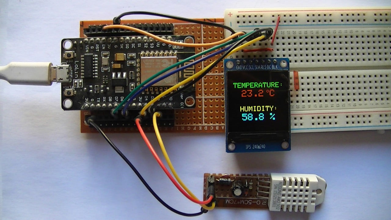
NodeMCU with ST7789 TFT and DHT22 (AM2302) sensor circuit:
Project circuit schematic diagram is shown below.
The DHT22 (AM2302) sensor has 4 pins (from left to right):
Pin 1 is power supply pin, connected to NodeMCU 3V3 pin,
Pin 2: data output pin, connected to NodeMCU pin D2,
Pin 3: not connected pin,
Pin 4: GND (ground), connected to NodeMCU GND pin.
A pull-up resistor of 4.7k ohm is required because the DHT22 sensor has an open drain output.
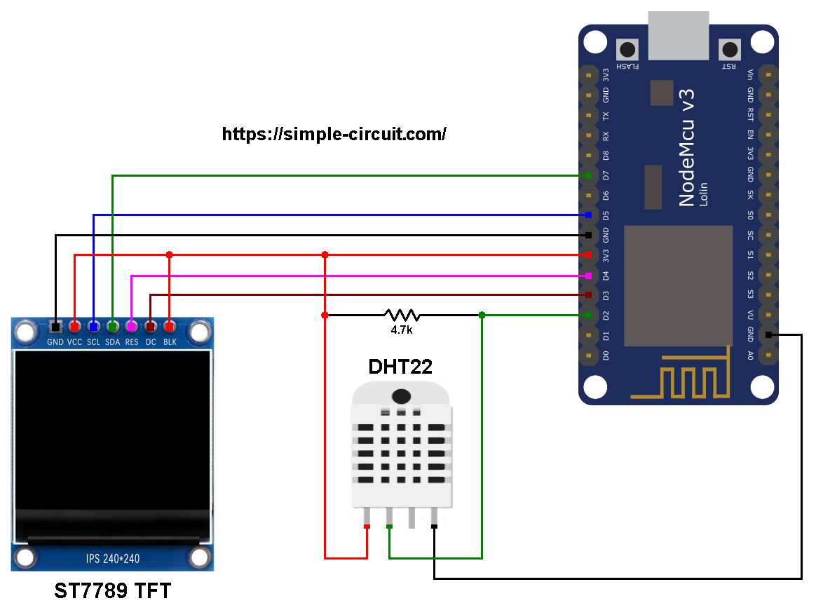
The ST7789 display module shown in project circuit diagram has 7 pins: (from right to left): GND (ground), VCC, SCL (serial clock), SDA (serial data), RES (reset), DC (or D/C: data/command) and BLK (back light).
The ST7789 TFT display module is connected to the NodeMCU board as follows:
GND is connected to pin GND of the NodeMCU board,
VCC and BL are connected to pin 3V3,
SCL pin is connected to D5 (ESP8266EX GPIO14),
SDA pin is connected to D7 (ESP8266EX GPIO13),
RES pin is connected to D4 (ESP8266EX GPIO2),
DC pin is connected to D3 (ESP8266EX GPIO0).
If the display module has a CS pin (Chip Select) then it should be connected to NodeMCU pin D8 (GPIO15).
Connecting the BLK pin is optional. The back light turns off when the BLK pin connected to the ground (GND).
Pins D5 (GPIO14) and D7 (GPIO13) are hardware SPI module pins of the ESP8266EX microcontroller respectively for SCK (serial clock) and MOSI (master-out slave-in).
NodeMCU with ST7789 TFT and DHT22 (AM2302) sensor code:
The following Arduino code requires 3 libraries from Adafruit Industries:
The first library is a driver for the ST7789 TFT display which can be installed from Arduino IDE library manager (Sketch —> Include Library —> Manage Libraries …, in the search box write “st7789” and install the one from Adafruit).
The second library is Adafruit graphics library which can be installed also from Arduino IDE library manager.
The 3rd library is for the DHT22 sensor, it may be installed using library manager (in the search box write “dht” and choose the one from Adafruit).
The 3 libraries can be installed manually, first download them from the following 3 links:
Adafruit ST7789 TFT library —-> direct link
Adafruit graphics library —-> direct link
Adafruit DHT library —-> direct link
You may need to install Adafruit Unified Sensor library if it’s not already installed, download link is below:
Adafruit Unified Sensor library —-> direct link
After the download, go to Arduino IDE —> Sketch —> Include Library —> Add .ZIP Library … and browse for the .zip file (previously downloaded).
The same thing for other library files.
Hints:
The 3 libraries are included in the main code as follows:
1 2 3 | #include <Adafruit_GFX.h> // Core graphics library #include <Adafruit_ST7789.h> // Hardware-specific library for ST7789 #include <DHT.h> // Adafruit DHT library code |
The connection of ST7789 TFT display with the NodeMCU is as shown below where the display is connected to hardware SPI module of the NodeMCU (pins: SCK and MOSI):
1 2 3 4 5 6 7 8 | // ST7789 TFT module connections #define TFT_DC D3 // TFT DC pin is connected to NodeMCU pin D3 (GPIO0) #define TFT_RST D4 // TFT RST pin is connected to NodeMCU pin D4 (GPIO2) #define TFT_CS D8 // TFT CS pin is connected to NodeMCU pin D8 (GPIO15) // initialize ST7789 TFT library with hardware SPI module // SCK (CLK) ---> NodeMCU pin D5 (GPIO14) // MOSI(DIN) ---> NodeMCU pin D7 (GPIO13) Adafruit_ST7789 tft = Adafruit_ST7789(TFT_CS, TFT_DC, TFT_RST); |
And the TFT display is initialized using the following command:
1 2 | // if the display has CS pin try with SPI_MODE0 tft.init(240, 240, SPI_MODE2); // init ST7789 display 240x240 pixel |
Definition of sensor type, its data pin connection and the initialization of the DHT library:
1 2 3 | #define DHTPIN D2 // DHT22 data pin is connected to NodeMCU pin D2 (GPIO4) #define DHTTYPE DHT22 // DHT22 sensor is used DHT dht22(DHTPIN, DHTTYPE); // configure DHT library |
Rest of code is described through comments.
Full Arduino code:
1 2 3 4 5 6 7 8 9 10 11 12 13 14 15 16 17 18 19 20 21 22 23 24 25 26 27 28 29 30 31 32 33 34 35 36 37 38 39 40 41 42 43 44 45 46 47 48 49 50 51 52 53 54 55 56 57 58 59 60 61 62 63 64 65 66 67 68 69 70 71 72 73 74 75 76 77 78 79 80 81 | /************************************************************************** * * Interfacing ESP8266 NodeMCU (ESP-12E) with ST7789 TFT display and * DHT22 (AM2302) digital humidity & temperature sensor. * This is a free software with NO WARRANTY. * http://simple-circuit.com/ * *************************************************************************/ #include <Adafruit_GFX.h> // Core graphics library #include <Adafruit_ST7789.h> // Hardware-specific library for ST7789 #include <DHT.h> // Adafruit DHT library code // ST7789 TFT module connections #define TFT_DC D3 // TFT DC pin is connected to NodeMCU pin D3 (GPIO0) #define TFT_RST D4 // TFT RST pin is connected to NodeMCU pin D4 (GPIO2) #define TFT_CS D8 // TFT CS pin is connected to NodeMCU pin D8 (GPIO15) // initialize ST7789 TFT library with hardware SPI module // SCK (CLK) ---> NodeMCU pin D5 (GPIO14) // MOSI(DIN) ---> NodeMCU pin D7 (GPIO13) Adafruit_ST7789 tft = Adafruit_ST7789(TFT_CS, TFT_DC, TFT_RST); #define DHTPIN D2 // DHT22 data pin is connected to NodeMCU pin D2 (GPIO4) #define DHTTYPE DHT22 // DHT22 sensor is used DHT dht22(DHTPIN, DHTTYPE); // configure DHT library void setup(void) { // if the display has CS pin try with SPI_MODE0 tft.init(240, 240, SPI_MODE2); // init ST7789 display 240x240 pixel // if the screen is flipped, remove this command tft.setRotation(2); // fill the screen with black color tft.fillScreen(ST77XX_BLACK); tft.setTextWrap(false); // turn off text wrap option tft.setTextColor(ST77XX_GREEN, ST77XX_BLACK); // set text color to green and black background tft.setTextSize(3); // text size = 3 tft.setCursor(15, 40); // move cursor to position (15, 27) pixel tft.print("TEMPERATURE:"); tft.setTextColor(ST77XX_YELLOW, ST77XX_BLACK); // set text color to yellow and black background tft.setCursor(43, 140); // move cursor to position (15, 27) pixel tft.print("HUMIDITY:"); tft.setTextSize(4); // text size = 4 // print °C tft.drawCircle(161, 77, 4, ST77XX_RED); // print degree symbol ( ° ) tft.drawCircle(161, 77, 5, ST77XX_RED); tft.setCursor(170, 71); tft.setTextColor(ST77XX_RED, ST77XX_BLACK); // set text color to red with black background tft.print("C"); // initialize DHT22 sensor dht22.begin(); } // main loop void loop() { delay(1000); // wait a second // read humidity in rH% int Humi = dht22.readHumidity() * 10; // read temperature in degrees Celsius int Temp = dht22.readTemperature() * 10; // print temperature (in °C) tft.setCursor(26, 71); tft.setTextColor(ST77XX_RED, ST77XX_BLACK); // set text color to red with black background if(Temp < 0) // if temperature < 0 tft.printf("-%02u.%1u", (abs(Temp)/10)%100, abs(Temp) % 10); else // temperature >= 0 tft.printf(" %02u.%1u", (Temp/10)%100, Temp % 10); // print humidity (in %) tft.setCursor(50, 171); tft.setTextColor(ST77XX_CYAN, ST77XX_BLACK); // set text color to cyan and black background tft.printf("%02u.%1u %%", (Humi/10)%100, Humi % 10); } // end of code. |
Related Project:
ESP8266 NodeMCU Interface with ST7789 TFT and DHT11 Sensor
Discover more from Simple Circuit
Subscribe to get the latest posts sent to your email.