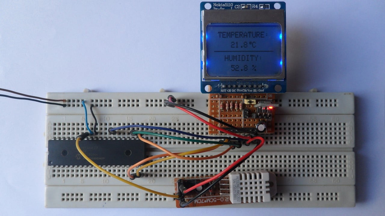
This is another PIC project that shows how to interface PIC18F46K22 microcontroller with Nokia 5110 (Nokia 3310) LCD and how to use its library.
In this project the Nokia 5110 LCD (84 x 48 pixel) is used to display temperature (in degree Celsius, °C) and humidity (in relative humidity percent, rH%) where DHT22 (equivalent to AM2302) digital humidity and temperature sensor is used.
MikroC PRO for PIC compiler is used in this project.
To see how to interface PIC18F46K22 MCU with Nokia 5110 LCD using mikroC, visit this post:
Interfacing PIC MCU with Nokia 5110 LCD | mikroC Projects
Hardware Required:
- PIC18F46K22 microcontroller —-> datasheet
- Nokia 5110 LCD module
- DHT22 (AM2302) humidity and temperature sensor —-> datasheet
- AMS1117 3V3 voltage regulator
- 10 uF capacitor
- 100 nF ceramic capacitor
- 5 x 3.3k ohm resistor
- 5 x 2.2k ohm resistor
- 4.7k ohm resistor
- 5V source
- Breadboard
- Jumper wires
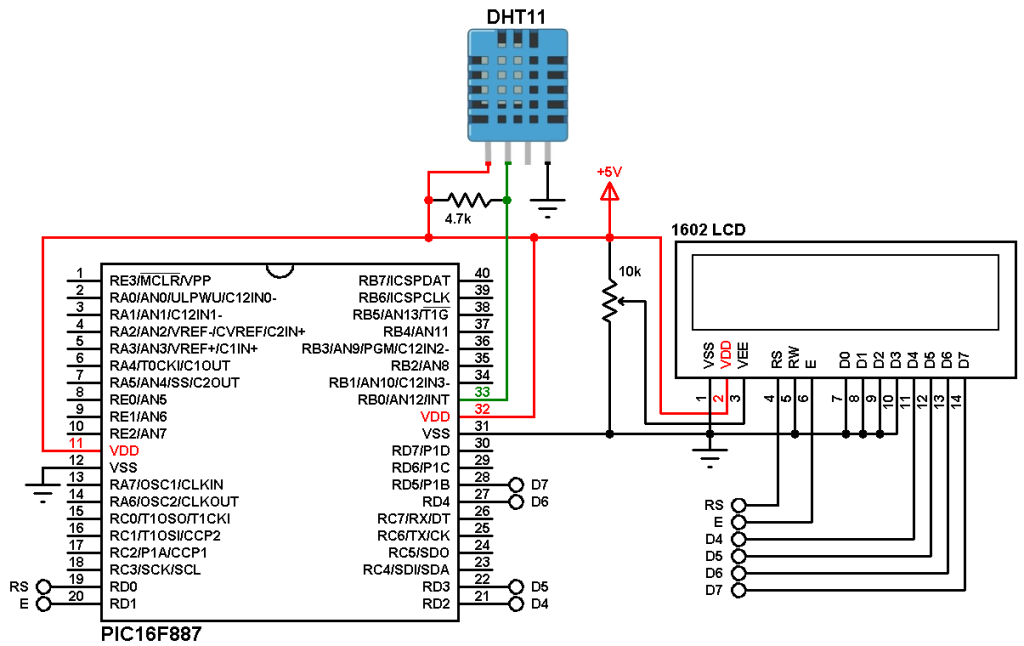
PIC18F46K22 with DHT22 sensor and Nokia 5110 LCD circuit:
The following image shows project circuit diagram.
The DHT22 sensor has 4 pins (from left to right):
Pin 1 is power supply pin, connected to circuit +5V,
Pin 2: data output pin, connected to PIC18F46K22 pin RB0 (#33),
Pin 3: not connected pin,
Pin 4: GND (ground), connected to circuit ground.
The 4.7k ohm resistor is needed because the DHT22 output is open drain.
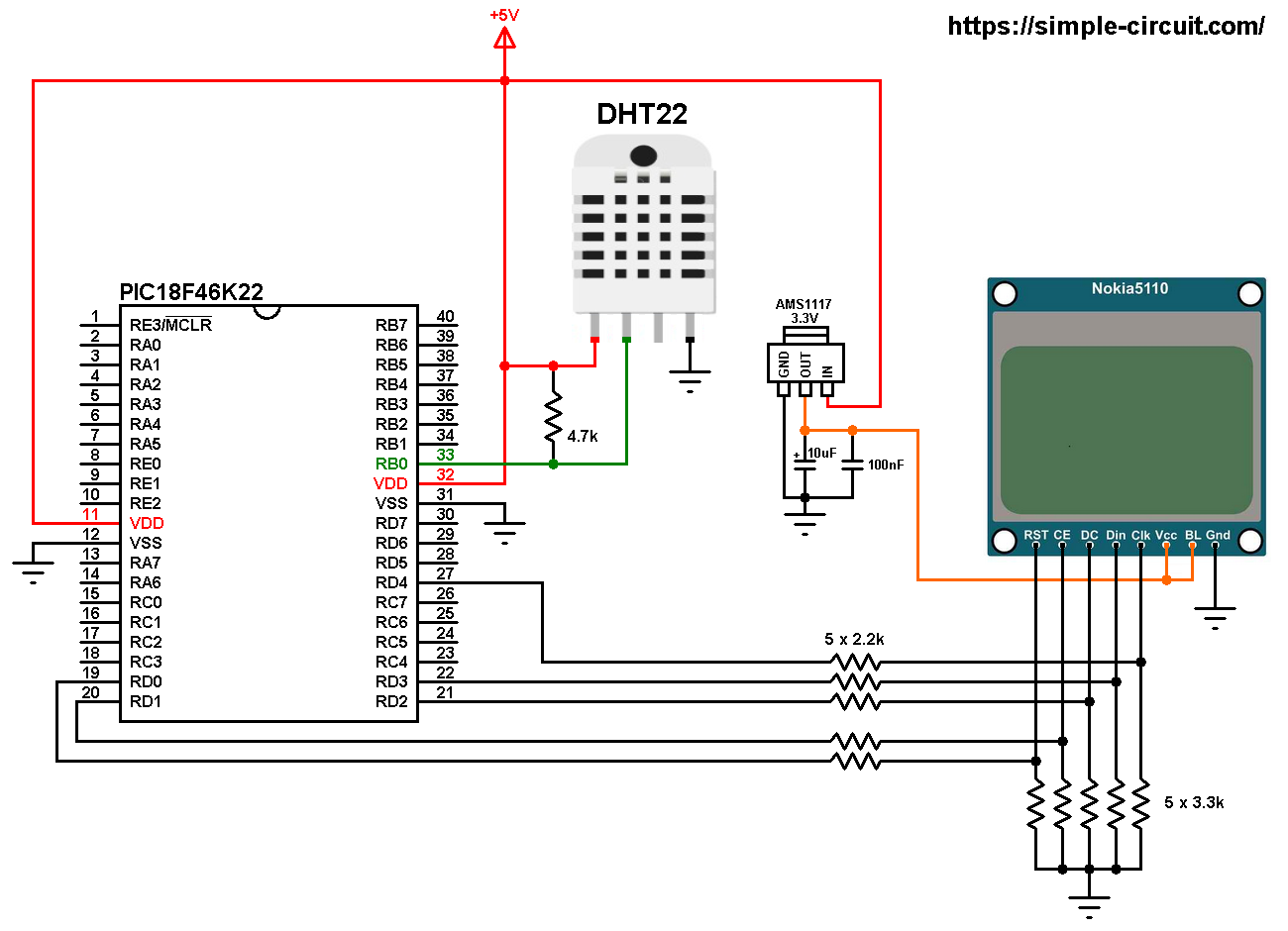
All the grounded terminals are connected together.
The Nokia 5110 which is shown in the circuit diagram has 8 pins (from left to right): RST (reset), CE (chip enable), DC (or D/C: data/command), Din (data in), Clk (clock), VCC (3.3V), BL (back light) and Gnd (ground).
The Nokia 5110 LCD works with 3.3V only (power supply and control lines). The LCD module is supplied with 3.3V which comes from the AMS1117 3V3 voltage regulator, this regulator steps down the 5V into 3.3V (supplies the LCD controller PCD8544 with regulated 3V3).
All PIC18F46K22 microcontroller output pins are 5V, connecting a 5V pin directly to the Nokia 5110 LCD may damage its controller circuit!
To connect the PIC18F46K22 to the LCD module, I used voltage divider for each line. That means there are 5 voltage dividers. Each voltage divider consists of 2.2k and 3.3k resistors, this drops the 5V into 3V which is sufficient.
So, the Nokia 5110 LCD pins are connected to PIC18F46K22 MCU as follows (each one through voltage divider):
RST (reset) pin is connected to pin RD0 (#19)
CE (chip enable) pin is connected to pin RD1 (#20)
DC (data/command) pin is connected to pin RD2 (#21)
DIN (data in) pin is connected to pin RD3 (#22)
CLK (clock) pin is connected to pin RD4 (#27)
VCC and BL are connected to AMS1117 3V3 regulator output pin and GND is connected to circuit ground (0V).
In this project the PIC18F46K22 microcontroller runs with its internal oscillator @ 16 MHz, MCLR pin is configured as an input pin.
PIC18F46K22 with DHT22 sensor and Nokia 5110 LCD C code:
The following C code is for mikroC PRO for PIC compiler, it was tested with version 7.2.0.
To be able to compile project C code, a driver for the Nokia 5110 LCD is required, download link is below. After you download the driver file which named NOKIA5110.C, add it to your project folder:
Nokia 5110 LCD library for mikroC compiler
The connection of the LCD pins with the microcontroller are defined in the C code as shown below:
1 2 3 4 5 6 7 8 | // Nokia 5110 LCD module connections // use software SPI #define LCD_RST RD0_bit // reset pin, optional! #define LCD_CS RD1_bit // chip select pin, optional! #define LCD_DC RD2_bit // data/command pin #define LCD_DAT RD3_bit // data-in pin (MOSI) #define LCD_CLK RD4_bit // clock pin // end LCD module connections |
And the DHT22 data pin is defined as:
1 2 3 | // DHT22 pin connection (here data pin is connected to pin RB0) #define DHT22_PIN RB0_bit #define DHT22_PIN_DIR TRISB0_bit |
Functions used in the code:
void Start_Signal(void): sends start signal to the DHT22 sensor.
char Check_Response(): checks response signal of the DHT22 sensor (after sending the start signal using the previous function), returns 1 if OK and 0 if error.
void Read_Data(unsigned short* dht_data): reads 1 byte from the DHT22 sensor which is saved to the variable dht_data.
If there is a problem with the DHT22 sensor (for example bad connection) the display will display Sensor (instead of the temperature value) Error! (instead of the humidity value), and if there is a check sum error (for example due to wrong data reading) the display will display Checksum (instead of the temperature value) Error! (instead of the humidity value).
Timer0 module is used to measure pulse widths (high and low), it’s configured to work as 8-bit timer/counter and prescaler = 4 (increment by 1 every 1 microsecond ==> clock input = 1MHz).
Timer0 clock input = Fosc/(4 x prescaler) = 16MHz/(4 x 4) = 1MHz.
Rest of code is described through comments.
Full mikroC code:
1 2 3 4 5 6 7 8 9 10 11 12 13 14 15 16 17 18 19 20 21 22 23 24 25 26 27 28 29 30 31 32 33 34 35 36 37 38 39 40 41 42 43 44 45 46 47 48 49 50 51 52 53 54 55 56 57 58 59 60 61 62 63 64 65 66 67 68 69 70 71 72 73 74 75 76 77 78 79 80 81 82 83 84 85 86 87 88 89 90 91 92 93 94 95 96 97 98 99 100 101 102 103 104 105 106 107 108 109 110 111 112 113 114 115 116 117 118 119 120 121 122 123 124 125 126 127 128 129 130 131 132 133 134 135 136 137 138 139 140 141 142 143 144 145 146 147 148 149 150 151 152 153 154 155 156 157 158 159 160 161 162 163 164 165 166 167 168 169 170 171 172 173 174 175 176 177 178 179 180 181 182 183 184 185 186 187 | /************************************************************************************** Interfacing PIC18F46K22 microcontroller with Nokia 5110 LCD and DHT22 sensor. DHT22 (AM2302) is a digital humidity and temperature sensor. C Code for mikroC PRO for PIC compiler. Internal oscillator used @ 16MHz Configuration words: CONFIG1H = 0x0028 CONFIG2L = 0x0018 CONFIG2H = 0x003C CONFIG3H = 0x0037 CONFIG4L = 0x0081 CONFIG5L = 0x000F CONFIG5H = 0x00C0 CONFIG6L = 0x000F CONFIG6H = 0x00E0 CONFIG7L = 0x000F CONFIG7H = 0x0040 This is a free software with NO WARRANTY. http://simple-circuit.com/ ***************************************************************************************/ // Nokia 5110 LCD module connections // use software SPI #define LCD_RST RD0_bit // reset pin, optional! #define LCD_CS RD1_bit // chip select pin, optional! #define LCD_DC RD2_bit // data/command pin #define LCD_DAT RD3_bit // data-in pin (MOSI) #define LCD_CLK RD4_bit // clock pin // end LCD module connections // include Nokia 5110 LCD driver source file #include <NOKIA5110.c> // DHT22 pin connection (here data pin is connected to pin RB0) #define DHT22_PIN RB0_bit #define DHT22_PIN_DIR TRISB0_bit // send start signal to the sensor void Start_Signal(void) { DHT22_PIN = 0; // connection pin output low DHT22_PIN_DIR = 0; // configure connection pin as output delay_ms(25); // wait 25 ms DHT22_PIN = 1; // connection pin output high delay_us(30); // wait 30 us DHT22_PIN_DIR = 1; // configure connection pin as input } // check sensor response char Check_Response(void) { TMR0L = 0; // rest Timer0 low register // wait until DHT22_PIN becomes high (checking of 80µs low time response) while(!DHT22_PIN && TMR0L < 100) ; if(TMR0L >= 100) // if response time > 80µS ==> response error return 0; // return 0 (device has a problem with response) TMR0L = 0; // rest Timer0 low register // wait until DHT22_PIN becomes low (checking of 80µs high time response) while(DHT22_PIN && TMR0L < 100) ; if(TMR0L >= 100) // if response time > 80µS ==> response error return 0; // return 0 (device has a problem with response) return 1; // return 1 (response OK) } // data read function void Read_Data(unsigned short* dht_data) { char i; *dht_data = 0; for(i = 0; i < 8; i++) { TMR0L = 0; // rest Timer0 low register while(!DHT22_PIN) // wait until DHT22_PIN becomes high { if(TMR0L > 80) // if low time > 80µS ==> Time out error (Normally it takes 50µs) return; // return (timeout error) } TMR0L = 0; // rest Timer0 low register while(DHT22_PIN) // wait until DHT22_PIN becomes low { if(TMR0L > 80) // if high time > 80µS ==> Time out error (normally it takes 26-28µs for 0 and 70µs for 1) return; // return (timeout error) } if(TMR0L > 40) // if high time > 40µS ==> sensor sent 1 *dht_data |= (1 << (7 - i)); // set bit (7 - i) } return; // return (data read OK) } // main function void main() { OSCCON = 0x70; // set internal oscillator to 16MHz ANSELB = 0; // configure all PORTB pins as digital ANSELD = 0; // configure all PORTD pins as digital TRISD = 0; // configure all PORTD pins as outputs T0CON = 0x41; // configure Timer0 module (8-bit timer & prescaler = 4) LCD_Begin(); // initialize the LCD LCD_Clear(); // clear the display buffer LCD_SetContrast(55); // set LCD contrast LCD_DrawHLine(0, 23, LCDWIDTH, BLACK); // draw horizontal line LCD_TextSize(1); // set text size to 1 LCD_GotoXY(6, 0); // move cursor to position (6, 0) pixel LCD_Print("TEMPERATURE:"); LCD_GotoXY(15, 28); // move cursor to position (15, 28) pixel LCD_Print("HUMIDITY:"); LCD_Display(); // update the screen while(1) { char T_Byte1, T_Byte2, RH_Byte1, RH_Byte2, CheckSum; unsigned int Temp, Humi; char temp_a[9], humi_a[8]; char sensor_ok = 0; TMR0ON_bit = 1; // enable Timer0 module Start_Signal(); // send a start signal to the sensor if(Check_Response()) // check if there is a response from sensor (if OK start reading humidity and temperature data) { // response OK ==> read (and save) data from the DHT22 sensor Read_Data(&RH_Byte1); // read humidity 1st byte Read_Data(&RH_Byte2); // read humidity 2nd byte Read_Data(&T_Byte1); // read temperature 1st byte Read_Data(&T_Byte2); // read temperature 2nd byte Read_Data(&CheckSum); // read checksum TMR0ON_bit = 0; // disable Timer0 module // test if all data were sent correctly if( CheckSum == ((RH_Byte1 + RH_Byte2 + T_Byte1 + T_Byte2) & 0xFF) ) { sensor_ok = 1; Humi = (RH_Byte1 << 8) | RH_Byte2; Temp = (T_Byte1 << 8) | T_Byte2; if(Temp & 0x8000) { // if temperature is negative Temp = Temp & 0x7FFF; sprinti(temp_a, "-%02u.%01u C ", Temp/10, Temp % 10); } else // otherwise (temperature is positive) sprinti(temp_a, " %02u.%01u C ", Temp/10, Temp % 10); if(humi >= 1000) // if humidity >= 100.0 rH% sprinti(humi_a, "%03u.%01u %%", Humi/10, Humi % 10); else sprinti(humi_a, " %02u.%01u %%", Humi/10, Humi % 10); } else { sprinti(temp_a, "Checksum"); sprinti(humi_a, " Error!"); } } else { sprinti(temp_a, " Sensor "); sprinti(humi_a, " Error!"); } // print sensor data on the display LCD_GotoXY(18, 12); LCD_Print(temp_a); LCD_GotoXY(18, 40); LCD_Print(humi_a); if(sensor_ok) LCD_DrawRect(50, 12, 3, 3, BLACK); // print degree symblos ( ° ) LCD_Display(); // update the screen delay_ms(1000); // wait a second } } // end of code. |
Discover more from Simple Circuit
Subscribe to get the latest posts sent to your email.