This tutorial shows how to interface Microchip PIC18F46K22 8-bit microcontroller with ST7789 TFT display.
The ST7789 TFT is a color display that uses SPI protocol. This display is an IPS display, it comes in different sizes (1.3″, 1.54″ …) but all of them should have the same resolution of 240×240 pixel.
This module works with 3.3V only, connecting it directly to a 5V system will not work and may damage its controller circuit!
The compiler used in this project is mikroElektronika mikroC PRO for PIC.
SPI: Serial Peripheral Interface.
IPS: In-Plane Switching.
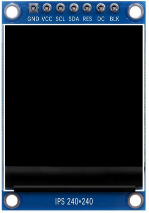
The following image shows a ST7789 display module provided by Adafruit Industries:

Another version of the ST7789 display module is shown below. This one has no CS (chip select) pin, its internally attached to GND:
Project Hardware Required:
- PIC18F46K22 microcontroller —-> datasheet
- ST7789 TFT display module (1.3″, 1.54″ …)
- AMS1117 3V3 voltage regulator
- 10 uF capacitor
- 100 nF ceramic capacitor
- 4 x 3.3k ohm resistor (+1 if the display module has CS pin)
- 4 x 2.2k ohm resistor (+1 if the display module has CS pin)
- 5V source
- Breadboard
- Jumper wires
Interfacing PIC18F46K22 MCU with ST7789 TFT circuit:
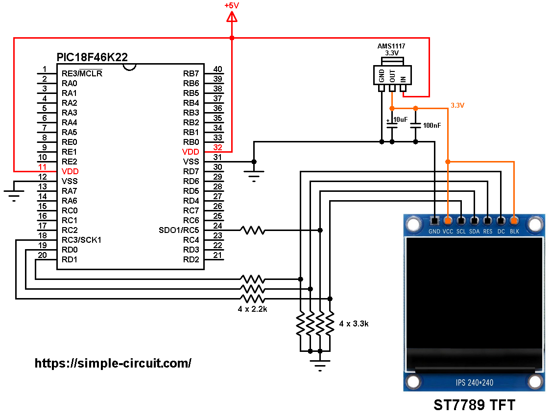
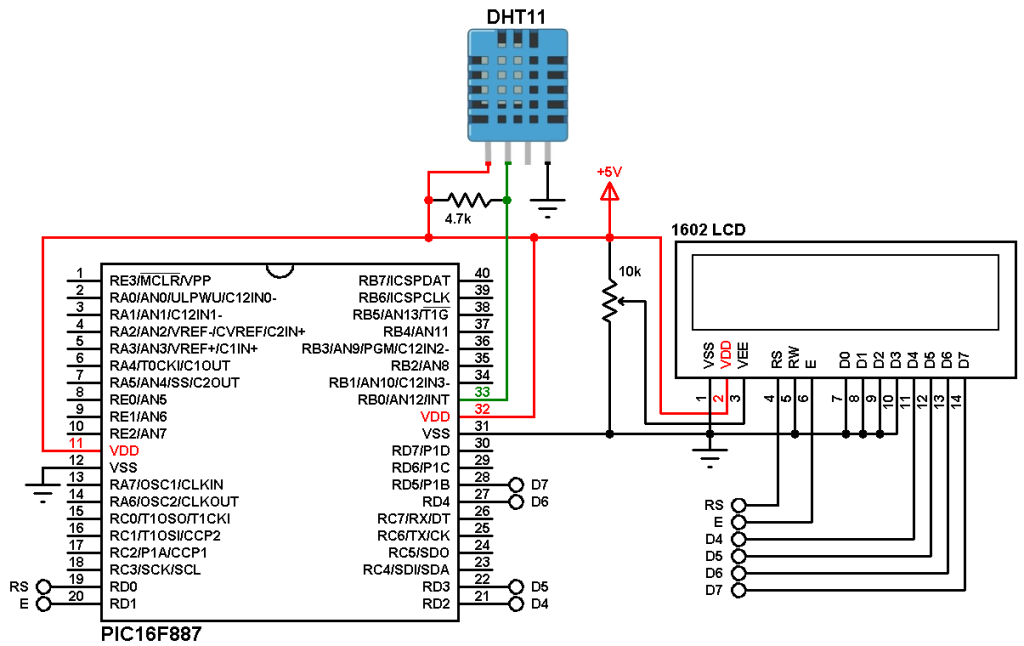
Project circuit schematic diagram is shown below.
The ST7789 display module shown in project circuit diagram has 7 pins: (from right to left): GND (ground), VCC, SCL (serial clock), SDA (serial data), RES (reset), DC (or D/C: data/command) and BLK (back light).
Connecting the BLK pin is optional. The back light of the display turns off when the BLK pin is connected to the ground (GND).
All the grounded terminals are connected together.
The ST7789 TFT display works with 3.3V only (power supply and control lines). The display module is supplied with 3.3V that comes from the AMS1117 3V3 voltage regulator, this regulator steps down the 5V into 3.3V (supplies the display controller with regulated 3V3).
All PIC18F46K22 microcontroller output pins are 5V, connecting a 5V pin directly to the ST7789 TFT display may damage its controller circuit!
To connect the PIC18F46K22 with the display module, I used voltage divider for each line. This means there are 4 voltage dividers. Each voltage divider consists of 2.2k and 3.3k resistors, this drops the 5V into 3V which is sufficient.
If the display module has a CS pin (Chip Select) then it should be connected to the PIC18F46K22 microcontroller through another voltage divider (for example connecting it to pin RD2).
The PIC18F46K22 microcontroller has 2 hardware SPI modules (MSSP1 and MSSP2 modules).
In this project SPI1 module is used with SCK1 on pin RC3 (#18) and SDO1 (MOSI) on pin RC5 (#24). SCK1 and SDO1 pins of the PIC18F46K22 MCU are respectively connected to SCL and SDA pins of the ST7789 display module.
So, the ST7789 TFT display is connected to the PIC18F46K22 MCU as follows (each one through voltage divider):
RST pin is connected to pin RD0 (#19),
D/C pin is connected to pin RD1 (#21),
SCL pin is connected to pin RC3 (#18),
SDA pin is connected to pin RC5 (#24).
In this project the PIC18F46K22 microcontroller runs with its internal oscillator @ 64 MHz (16 MIPS), MCLR pin is configured as an input pin.
With clock frequency of 64MHz we get a maximum data transfer rate of 16 Mbps.
Interfacing PIC18F46K22 MCU with ST7789 TFT C code:
The following C code is for mikroC PRO for PIC compiler, it was tested with version 7.6.0.
To be able to compile project C code with no error, 2 libraries are required:
The first library is a driver for the ST7789 TFT display, its full name (with extension) is ST7789.c, download link is below:
ST7789 TFT display library for mikroC compiler
The second library is graphics library, its full name is GFX_Library.c, download link is the one below:
Graphics library for mikroC compiler
after the download of the 2 library files, add both of them to the project folder.
The default connection setting of the mikroC ST7789 TFT library is hardware SPI1 module (SPI1 module must be initialized before initiating the display). Instead of hardware SPI1 module, software SPI or hardware SPI2 module can be used.
If TFT data pin (TFT_DIN) and clock pin (TFT_SCK) are defined in the main code (before #include “ST7789.c”) then the library will automatically use software SPI.
example (respectively, TFT_DIN and TFT_SCK are connected to RD3 and RD4):
#define TFT_DIN RD3_bit
#define TFT_SCK RD4_bit
If the line below is defined then the library will use hardware SPI2 module:
#define ST7789_HARD_SPI2
Hints:
The 2 library files are included in the main code as shown below:
1 2 | #include "ST7789.c" // include ST7789 display driver #include "GFX_Library.c" // include graphics library source code |
As mentioned above, the ST7789 TFT is connected to PIC18F46K22 microcontroller SPI1 module pins (SCK1 and SDO1) which is initialized as shown below.
Note that if the display doesn’t work uncomment the second SPI1 initializing line and the first one should be commented (or removed).
1 2 3 4 | // initialize SPI1 module SPI1_Init_Advanced(_SPI_MASTER_OSC_DIV4, _SPI_DATA_SAMPLE_MIDDLE, _SPI_CLK_IDLE_HIGH, _SPI_LOW_2_HIGH); // if it doesn't work try with this (mode 0) //SPI1_Init_Advanced(_SPI_MASTER_OSC_DIV4, _SPI_DATA_SAMPLE_MIDDLE, _SPI_CLK_IDLE_LOW, _SPI_LOW_2_HIGH); |
The other pins: RST and DC are defined as shown below.
If the display module has a CS pin uncomment its related lines (#define TFT_CS and #define TFT_CS_DIR) and connect it to RD2 pin of the microcontroller through voltage divider.
1 2 3 4 5 6 7 | // define ST7789 TFT module pin connections #define TFT_RST RD0_bit // reset pin, optional! #define TFT_DC RD1_bit // data/command pin //#define TFT_CS RD2_bit // chip select pin, use it if the display has CS pin #define TFT_RST_DIR TRISD0_bit #define TFT_DC_DIR TRISD1_bit //#define TFT_CS_DIR TRISD2_bit |
Rest of code is described through comments.
Full mikroC code:
1 2 3 4 5 6 7 8 9 10 11 12 13 14 15 16 17 18 19 20 21 22 23 24 25 26 27 28 29 30 31 32 33 34 35 36 37 38 39 40 41 42 43 44 45 46 47 48 49 50 51 52 53 54 55 56 57 58 59 60 61 62 63 64 65 66 67 68 69 70 71 72 73 74 75 76 77 78 79 80 81 82 83 84 85 86 87 88 89 90 91 92 93 94 95 96 97 98 99 100 101 102 103 104 105 106 107 108 109 110 111 112 113 114 115 116 117 118 119 120 121 122 123 124 125 126 127 128 129 130 131 132 133 134 135 136 137 138 139 140 141 142 143 144 145 146 147 148 149 150 151 152 153 154 155 156 157 158 159 160 161 162 163 164 165 166 167 168 169 170 171 172 173 174 175 176 177 178 179 180 181 182 183 184 185 186 187 188 189 190 191 192 193 194 195 196 197 198 199 200 201 202 203 204 205 206 207 208 209 210 211 212 213 214 215 216 217 218 219 220 221 222 223 224 225 226 227 228 229 230 231 232 233 234 235 236 237 238 239 240 241 242 243 244 245 246 247 248 249 250 251 252 253 254 255 256 257 258 259 260 261 262 263 264 265 266 267 268 269 270 271 272 273 274 275 276 277 278 279 280 281 282 283 284 285 286 287 288 289 290 291 292 293 294 295 296 297 298 299 300 301 302 303 304 305 306 307 308 309 310 311 312 313 314 315 316 317 318 319 320 321 322 323 | /**************************************************************************** Interfacing PIC18F46K22 microcontroller with ST7789 SPI TFT display (240x240 pixel). Graphics test example. C Code for mikroC PRO for PIC compiler. Internal oscillator used @ 64MHz Configuration words: CONFIG1H = 0x0028 CONFIG2L = 0x0018 CONFIG2H = 0x003C CONFIG3H = 0x0037 CONFIG4L = 0x0081 CONFIG5L = 0x000F CONFIG5H = 0x00C0 CONFIG6L = 0x000F CONFIG6H = 0x00E0 CONFIG7L = 0x000F CONFIG7H = 0x0040 This is a free software with NO WARRANTY. http://simple-circuit.com/ ***************************************************************************** This is a library for several Adafruit displays based on ST77* drivers. Works with the Adafruit 1.8" TFT Breakout w/SD card ----> http://www.adafruit.com/products/358 The 1.8" TFT shield ----> https://www.adafruit.com/product/802 The 1.44" TFT breakout ----> https://www.adafruit.com/product/2088 as well as Adafruit raw 1.8" TFT display ----> http://www.adafruit.com/products/618 Check out the links above for our tutorials and wiring diagrams. These displays use SPI to communicate, 4 or 5 pins are required to interface (RST is optional). Adafruit invests time and resources providing this open source code, please support Adafruit and open-source hardware by purchasing products from Adafruit! Written by Limor Fried/Ladyada for Adafruit Industries. MIT license, all text above must be included in any redistribution *****************************************************************************/ // define ST7789 TFT module pin connections #define TFT_RST RD0_bit // reset pin, optional! #define TFT_DC RD1_bit // data/command pin //#define TFT_CS RD2_bit // chip select pin, use it if the display has CS pin #define TFT_RST_DIR TRISD0_bit #define TFT_DC_DIR TRISD1_bit //#define TFT_CS_DIR TRISD2_bit #include "ST7789.c" // include ST7789 display driver #include "GFX_Library.c" // include graphics library source code void testlines(uint16_t color) { uint8_t x, y; display_fillScreen(ST7789_BLACK); for (x=0; x < display_width; x+=6) { display_drawLine(0, 0, x, display_height-1, color); } for (y=0; y < display_height; y+=6) { display_drawLine(0, 0, display_width-1, y, color); } display_fillScreen(ST7789_BLACK); for (x=0; x < display_width; x+=6) { display_drawLine(display_width-1, 0, x, display_height-1, color); } for (y=0; y < display_height; y+=6) { display_drawLine(display_width-1, 0, 0, y, color); } display_fillScreen(ST7789_BLACK); for (x=0; x < display_width; x+=6) { display_drawLine(0, display_height-1, x, 0, color); } for (y=0; y < display_height; y+=6) { display_drawLine(0, display_height-1, display_width-1, y, color); } display_fillScreen(ST7789_BLACK); for (x=0; x < display_width; x+=6) { display_drawLine(display_width-1, display_height-1, x, 0, color); } for (y=0; y < display_height; y+=6) { display_drawLine(display_width-1, display_height-1, 0, y, color); } } void testdrawtext(char *text, uint16_t color) { display_setCursor(0, 0); display_setTextColor(color, color); display_setTextWrap(true); display_puts(text); } void testfastlines(uint16_t color1, uint16_t color2) { uint8_t x, y; display_fillScreen(ST7789_BLACK); for (y=0; y < display_height; y+=5) { display_drawHLine(0, y, display_width, color1); } for (x=0; x < display_width; x+=5) { display_drawVLine(x, 0, display_height, color2); } } void testdrawrects(uint16_t color) { uint8_t x; display_fillScreen(ST7789_BLACK); for (x=0; x < display_width; x+=6) { display_drawRect(display_width/2 -x/2, display_height/2 -x/2 , x, x, color); } } void testfillrects(uint16_t color1, uint16_t color2) { uint8_t x; display_fillScreen(ST7789_BLACK); for (x=display_width-1; x > 6; x-=6) { display_fillRect(display_width/2 -x/2, display_height/2 -x/2 , x, x, color1); display_drawRect(display_width/2 -x/2, display_height/2 -x/2 , x, x, color2); } } void testfillcircles(uint8_t radius, uint16_t color) { uint8_t x, y; for (x=radius; x < display_width; x+=radius*2) { for (y=radius; y < display_height; y+=radius*2) { display_fillCircle(x, y, radius, color); } } } void testdrawcircles(uint8_t radius, uint16_t color) { uint16_t x, y; for (x=0; x < (uint16_t)display_width+radius; x+=radius*2) { for (y=0; y < (uint16_t)display_height+radius; y+=radius*2) { display_drawCircle(x, y, radius, color); } } } void testtriangles() { uint16_t color = 0xF800; uint8_t t, w = display_width / 2, x = display_height - 1, y = 0, z = display_width; display_fillScreen(ST7789_BLACK); for(t = 0 ; t <= 27; t++) { display_drawTriangle(w, y, y, x, z, x, color); x-=4; y+=4; z-=4; color+=60; } } void testroundrects() { uint16_t color = 100; uint8_t i, t; display_fillScreen(ST7789_BLACK); for(t = 0 ; t <= 4; t+=1) { uint8_t x = 0, y = 0, w = display_width - 2, h = display_height - 2; for(i = 0 ; i <= 26; i+=1) { display_drawRoundRect(x, y, w, h, 5, color); x+=2; y+=3; w-=4; h-=6; color+=1100; } color+=100; } } uint16_t millis = 0; void Interrupt() { TMR0IF_bit = 0; millis++; } void tftPrintTest() { float p = 3.1415926; display_setTextWrap(false); display_fillScreen(ST7789_BLACK); display_setCursor(0, 30); display_setTextColor(ST7789_RED, ST7789_BLACK); display_setTextSize(1); display_puts("Hello World!\r\n"); display_setTextColor(ST7789_YELLOW, ST7789_BLACK); display_setTextSize(2); display_puts("Hello World!\r\n"); display_setTextColor(ST7789_GREEN, ST7789_BLACK); display_setTextSize(3); display_puts("Hello World!\r\n"); display_setTextColor(ST7789_BLUE, ST7789_BLACK); display_setTextSize(4); display_printf("%7.2f", 1234.567); delay_ms(1500); display_setCursor(0, 0); display_fillScreen(ST7789_BLACK); display_setTextColor(ST7789_WHITE, ST7789_BLACK); display_setTextSize(0); display_puts("Hello World!\r\n"); display_setTextSize(1); display_setTextColor(ST7789_GREEN, ST7789_BLACK); display_printf("%8.6f", p); display_puts(" Want pi?\r\n"); display_puts(" \r\n"); display_printf("%6LX", 8675309); // print 8,675,309 out in HEX! display_puts(" Print HEX!\r\n"); display_puts(" \r\n"); display_setTextColor(ST7789_WHITE, ST7789_BLACK); display_puts("Sketch has been\r\n"); display_puts("running for: \r\n"); display_setTextColor(ST7789_MAGENTA, ST7789_BLACK); display_printf("%u", millis/1024); display_setTextColor(ST7789_WHITE, ST7789_BLACK); display_puts(" seconds."); } void mediabuttons() { // play display_fillScreen(ST7789_BLACK); display_fillRoundRect(81, 50, 78, 60, 8, ST7789_WHITE); display_fillTriangle(98, 60, 98, 100, 146, 80, ST7789_RED); delay_ms(500); // pause display_fillRoundRect(81, 130, 78, 60, 8, ST7789_WHITE); display_fillRoundRect(95, 138, 20, 45, 5, ST7789_GREEN); display_fillRoundRect(125, 138, 20, 45, 5, ST7789_GREEN); delay_ms(500); // play color display_fillTriangle(98, 60, 98, 100, 146, 80, ST7789_BLUE); delay_ms(50); // pause color display_fillRoundRect(95, 138, 20, 45, 5, ST7789_RED); display_fillRoundRect(125, 138, 20, 45, 5, ST7789_RED); // play color display_fillTriangle(98, 60, 98, 100, 146, 80, ST7789_GREEN); } // main function void main() { OSCCON = 0x70; // set internal oscillator to 16MHz PLLEN_bit = 1; // enable 4xPLL (clock frequency becomes 16 x 4 = 64MHz) ANSELC = 0; // configure all PORTC pins as digital ANSELD = 0; // configure all PORTD pins as digital // Timer0 interrupt configuration TMR0L = 0; // reset Timer0 low register T0CON = 0xC5; // use Timer0 as 8-bit timer with prescaler = 32 TMR0IF_bit = 0; // clear Timer0 interrupt flag GIE_bit = 1; // enable global interrupts TMR0IE_bit = 1; // enable Timer0 interrupt // initialize SPI1 module SPI1_Init_Advanced(_SPI_MASTER_OSC_DIV4, _SPI_DATA_SAMPLE_MIDDLE, _SPI_CLK_IDLE_HIGH, _SPI_LOW_2_HIGH); // if it doesn't work try with this (mode 0) //SPI1_Init_Advanced(_SPI_MASTER_OSC_DIV4, _SPI_DATA_SAMPLE_MIDDLE, _SPI_CLK_IDLE_LOW, _SPI_LOW_2_HIGH); // initialize the ST7789 display tft_init(); // fill screen with black display_fillScreen(ST7789_BLACK); // large block of text testdrawtext((char *)"Lorem ipsum dolor sit amet, consectetur adipiscing elit. Curabitur adipiscing ante sed nibh tincidunt feugiat. Maecenas enim massa, fringilla sed malesuada et, malesuada sit amet turpis. Sed porttitor neque ut ante pretium vitae malesuada nunc bibendum. Nullam aliquet ultrices massa eu hendrerit. Ut sed nisi lorem. In vestibulum purus a tortor imperdiet posuere. ", ST7789_WHITE); delay_ms(1000); // tft print function! tftPrintTest(); delay_ms(4000); // a single pixel display_drawPixel(display_width/2, display_height/2, ST7789_GREEN); delay_ms(500); // line draw test testlines(ST7789_YELLOW); delay_ms(500); // optimized lines testfastlines(ST7789_RED, ST7789_BLUE); delay_ms(500); testdrawrects(ST7789_GREEN); delay_ms(500); testfillrects(ST7789_YELLOW, ST7789_MAGENTA); delay_ms(500); display_fillScreen(ST7789_BLACK); testfillcircles(10, ST7789_BLUE); testdrawcircles(10, ST7789_WHITE); delay_ms(500); testroundrects(); delay_ms(500); testtriangles(); delay_ms(500); mediabuttons(); delay_ms(500); while(1) { display_invert(true); delay_ms(500); display_invert(false); delay_ms(500); } } // end of code. |
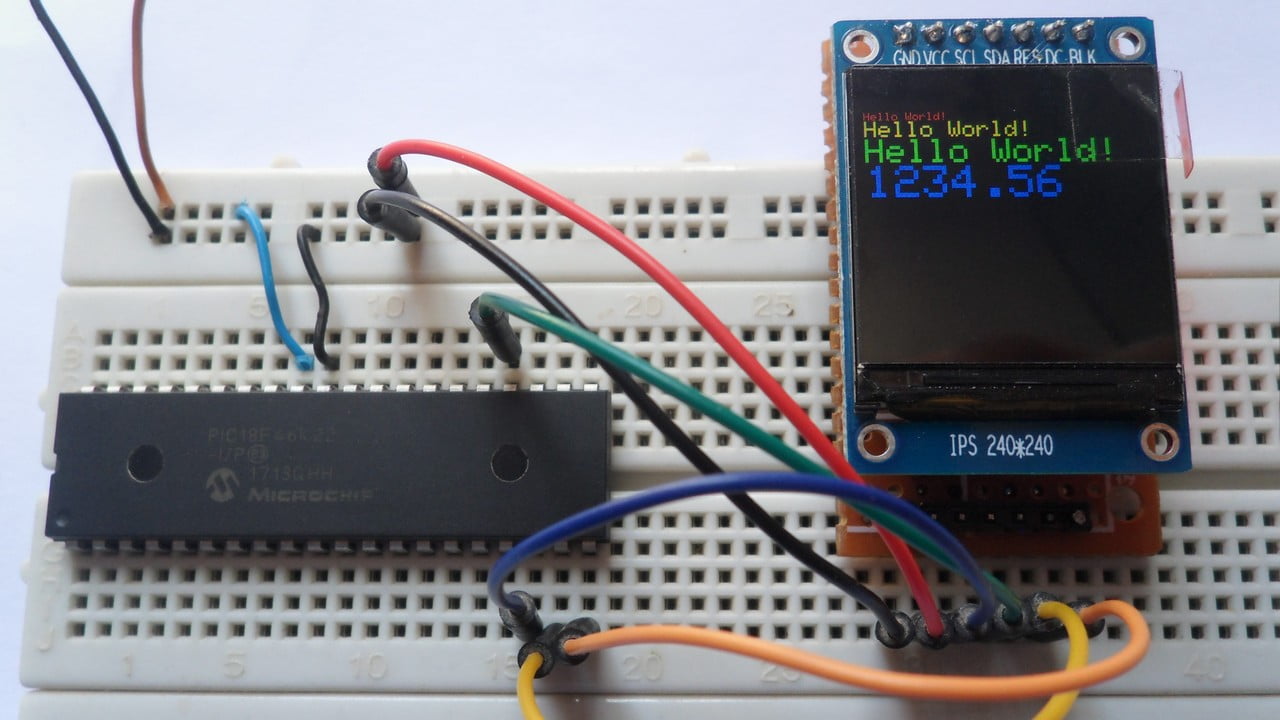
The video below shows my breadboard test circuit:
Discover more from Simple Circuit
Subscribe to get the latest posts sent to your email.
Using Mikroc and the PIC18F46K42, this project works perfectly but timer 1 stops running when tft_init(); is called. This chip uses the vectored interrupts. Would there be any reason for this? My project is on hold until i can sort this so any help would be appricated.
can i get xc8 library for thest7789 screen
Thanks to your effort, I have an 80 * 160 0.96 inch model. I can also use this library on it. but half of the screen works in an invisible spot. I hope I could explain what I mean. How can I set the screen resolution and rotation.
If you have any information on this subject, can you help?
Thanks for the reply but I had the two files in the project folder. I’ve managed to fix the issue of the missing routines by declaring the missing routines as “extern” (I believe it was the main.c) . Issue went away but then a million other compiling issues arose. I’ve followed all your instructions letter by letter and even made sure that my configurations bits matched your notes.
Either way, Ive managed to port all three files into one (for now) and now all the errors are gone and I can compile the code. I haven’t yet gotten the hardware to test it.
I would recommend you please review your instructions and see if the libraries are ok.
Thank you
The code _as it is_ should work properly and without any problem, it was tested with PIC18F46K22 and PIC18F4550 microcontrollers, compiler version is always 7.6.0
Try with this:
In the Library Manager uncheck all the built-in TFT libraries.
Undeclared identifier ‘SPI1_Write’ in expression st7789.c
Which MCU are you using?
Hi I am using PIC18F46K22 but getting the same error. Please help!!!
Hello.
Thanks for posting all this code.
When I compile, I get told that there are a number of undefined identifiers.
drawPixel, drawVLine, drawHline. I can’t find these subroutines anywhere. Any advice?
Thank you.
Make sure that you have added both files ST7789.C and GFX_Library.C to project folder!