PIC16F877A Timer0 module:
The Timer0 module timer/counter has the following features:
• 8-bit timer/counter
• Readable and writable
• 8-bit software programmable prescaler
• Internal or external clock select
• Interrupt on overflow from FFh to 00h
• Edge select for external clock
Timer mode is selected by clearing bit T0CS (OPTION_REG<5>). In Timer mode, the Timer0 module will increment every instruction cycle (without prescaler). If the TMR0 register is written, the increment is inhibited for the following two instruction cycles.
The user can work around this by writing an adjusted value to the TMR0 register.
Counter mode is selected by setting bit T0CS (OPTION_REG<5>). In Counter mode, Timer0 will increment either on every rising or falling edge of pin RA4/T0CKI. The incrementing edge is determined by the Timer0 Source Edge Select bit, T0SE (OPTION_REG<4>). Clearing bit T0SE selects the rising edge.
PIC16F877A Timer0 interrupt:
The TMR0 interrupt is generated when the TMR0 register overflows from FFh to 00h. This overflow sets bit TMR0IF (INTCON<2>). The interrupt can be masked by clearing bit TMR0IE (INTCON<5>). Bit TMR0IF must be cleared in software by the Timer0 module Interrupt Service Routine before re-enabling this interrupt. The TMR0 interrupt cannot awaken the processor from Sleep since the timer is shut-off during Sleep.
PIC16F877A Timer0 prescaler rate:
Prescaler rate of the timer0 can be: 2, 4, 8, 16, 32, 64, 128 or 256.
To enable the timer0 interrupt GIE bit (INTCON<7>) must be 1 which can be done using the following CCS C command:
enable_interrupts(GLOBAL) ;
Also T0IE bit (INTCON<7>) must be 1 which can be done using the following command:
enable_interrupts(INT_TIMER0) ;
Bit T0IF (INTCON<2>) must be cleared in software by the Timer0 module Interrupt Service Routine before re-enabling this interrupt and this is done using the following command:
clear_interrupt(INT_TIMER0) ;
We can set the timer0 preload value (initial value) using the following command:
set_timer0(preload_value) ;
where preload_value is an unsigned 8-bit number.
The clock source can be internal or external through RA4/T0CKI pin.
Timer0 prescaler rate and clock source and can be set using the following CCS line:
setup_timer_0(RTCC_INTERNAL|RTCC_DIV_256) ;
To compute the timer0 frequency use the following equation:
Timer0_freq = MCU_freq / {4 * Prescaler * (256 – TMR0)}
where TMR0 is timer0 preload value.
and:
peroid = 1/Timer0_freq which is time to interrupt.
PIC16F877A Timer0 interrupt example:
This is a simple example which uses PIC16F877A Timer0 interrupt to make an LED connected to RB0 blinking at a frequency about 1Hz.
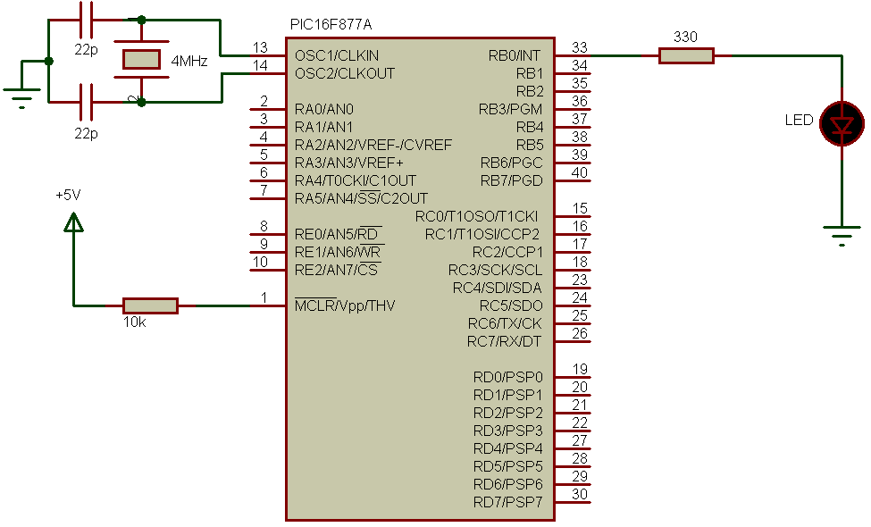
The circuit is simple there is only an LED, this LED keeps blinking without using the delay function.
PIC16F877A Timer0 interrupt example CCS PIC C code:
The timer is used to interrupt every 50ms and to make the LED ON for 500ms and OFF for 500ms, the interrupt must be interrupted 10 times, that why a variable i is used.
HS oscillator used with frequency of 4MHz.
1 2 3 4 5 6 7 8 9 10 11 12 13 14 15 16 17 18 19 20 21 22 23 24 25 26 27 28 29 30 31 | // PIC16F877A Timer0 interrupt // Timer0 is interrupted every 49.92ms (approximately 50ms) http://simple-circuit.com/ #include <16F877A.h> #use delay(crystal=4000000) byte i; #INT_TIMER0 void timer0_isr(void) { clear_interrupt(INT_TIMER0); set_timer0(61); i++; if(i > 9) { i = 0; output_toggle(PIN_B0); } } void main() { setup_timer_0(RTCC_INTERNAL|RTCC_DIV_256); // Configure Timer0 module with internal oscillator and 256 prescaler set_timer0(61); // Timer0 preload value = 61 clear_interrupt(INT_TIMER0); // Clear Timer0 interrupt flag bit enable_interrupts(INT_TIMER0); // Enable Timer0 interrupt enable_interrupts(GLOBAL); // Enable global interrupts output_low(PIN_B0); while(TRUE) ; // Endless loop } |
Discover more from Simple Circuit
Subscribe to get the latest posts sent to your email.