Related topics:
PIC16F877A Timer0 module and interrupt with CCS C compiler
PIC16F877A Timer2 module and interrupt with CCS C compiler
The Timer1 module is a 16-bit timer/counter consisting of two 8-bit registers (TMR1H and TMR1L) which are readable and writable. The TMR1 register pair (TMR1H:TMR1L) increments from 0000h to FFFFh and rolls over to 0000h.
This topic shows a simple example of the PIC16F877A Timer1 module and its interrupt.
PIC16F877A Timer1 interrupt:
The TMR1 interrupt, if enabled, is generated on overflow which is latched in interrupt flag bit, TMR1IF (PIR1<0>). This interrupt can be enabled/disabled by setting/clearing TMR1 interrupt enable bit, TMR1IE (PIE1<0>).
PIC16F877A Timer1 prescaler rate:
Prescaler rate of the timer1 can be: 1, 2, 4 or 8.
The following equation computes timer1 frequency:
Where TMR1 is preload value.
And Timer1 overflow time = 1/Timer1_freq
PIC16F877A Timer1 interrupt example:
This is a simple example which uses timer1 interrupt to make an LED connected to RB0 blinking at a frequency of 1Hz.
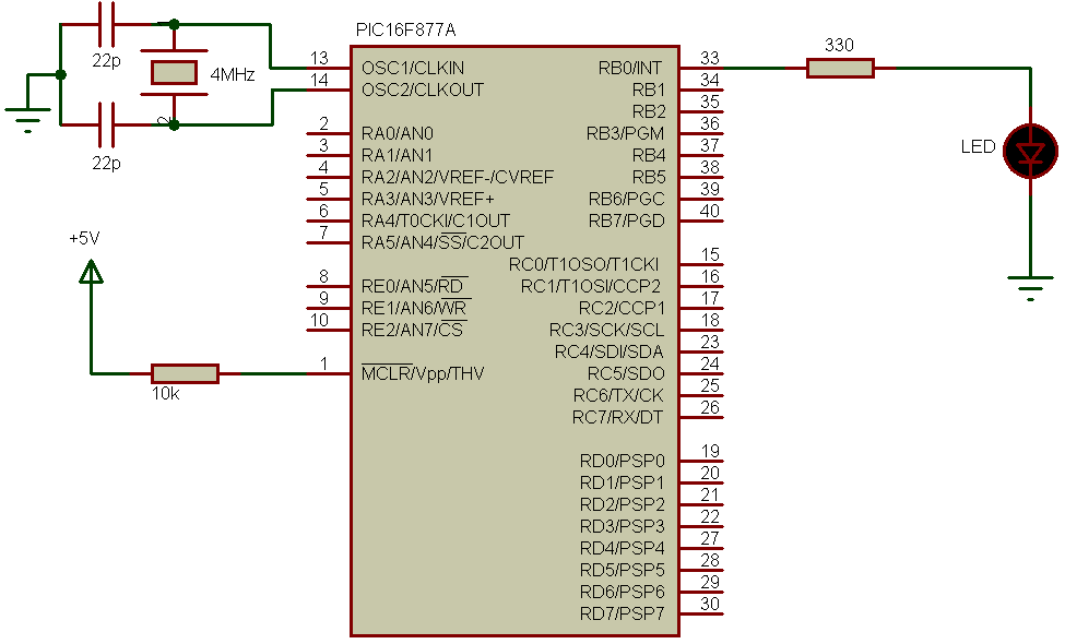
PIC16F877A Timer1 interrupt example CCS PIC C code:
The timer is used to interrupt every 500 ms which makes the LED ON for 500 ms and OFF for 500 ms. HS oscillator used with frequency of 4MHz.
1 2 3 4 5 6 7 8 9 10 11 12 13 14 15 16 17 18 19 20 21 22 23 24 25 26 | // PIC16F877A Timer1 interrupt // Timer1 is used to interrupt every 500ms // http://simple-circuit.com/ #include <16F877A.h> #use delay(crystal=4000000) #INT_TIMER1 void timer1_isr(void) { clear_interrupt(INT_TIMER1); set_timer1(3036); output_toggle(PIN_B0); } void main() { setup_timer_1 ( T1_INTERNAL | T1_DIV_BY_8 ); // Internal clock and prescaler 8 set_timer1(3036); // Preload value clear_interrupt(INT_TIMER1); // Clear Timer1 interrupt flag bit enable_interrupts(INT_TIMER1); // Enable Timer1 interrupt enable_interrupts(GLOBAL); // Enable global interrupts output_low(PIN_B0); while(TRUE) ; // Endless loop } |
Discover more from Simple Circuit
Subscribe to get the latest posts sent to your email.

Excelente trabalho!