The microcontroller PIC18F4550 has two CCP modules CCP1 and CCP2, the CCP1 module is implemented as a standard CCP module with Enhanced PWM capabilities. These include the provision for 2 or 4 output channels, user-selectable polarity, dead-band control and automatic shutdown and restart.
The Enhanced PWM mode provides additional PWM output options for a broader range of control applications. The module is a backward compatible version of the standard CCP module and offers up to four outputs, designated P1A through P1D.
This topic shows how to use the enhanced PWM as a Full-Bridge Mode to control DC motor speed and direction.
In Full-Bridge Output mode, four pins are used as outputs; however, only two outputs are active at a time. In the Forward mode, pin P1A is continuously active and pin P1D is modulated. In the Reverse mode, pin P1C is continuously active and pin P1B is modulated.
P1A, P1B, P1C and P1D outputs are multiplexed with the PORTC<2>, PORTD<5>, PORTD<6> and PORTD<7> data latches. The TRISC<2>, TRISD<5>, TRISD<6> and TRISD<7> bits must be cleared to make the P1A, P1B, P1C and P1D pins outputs.
The motor speed is controlled when the PWM duty cycle changes.
An H-Bridge circuit is used to reverse motor terminals which gives us the ability to change rotation direction.
Related topics:
DC motor speed control with PIC18F4550 and CCS PIC C
PIC18F4550 ADC example with CCS PIC C compiler
PIC18F4550 PWM example using CCS PIC C
DC motor control with PIC18F4550 microcontroller circuit:
The following circuit schematic shows project circuit.
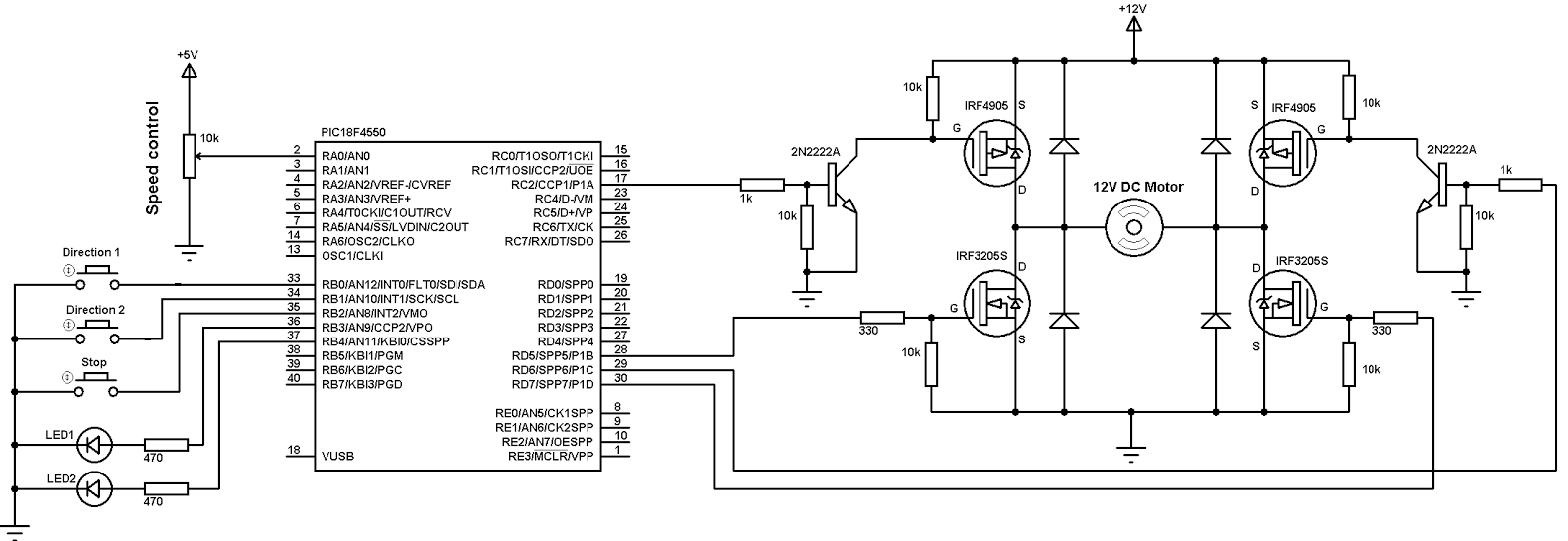
PORTB internal weak pull-ups are enabled in the software.
There are 3 pushbuttons in the circuit 2 of them to choose rotation direction and the other one stops the motor. The two LEDs indicate rotation direction, if Direction 1 button is pressed the motor moves in the first direction and LED 1 on and the same thing for Direction 2 button and LED 2. The motor speed is controlled from potentiometer connected to RA0 (analog channel 0). The microcontroller PIC18F4550 reads analog data from channel 0 and use the digital value to set the PWM duty cycle.
The PWM frequency is 500Hz.
The basic elements of the H-bridge are the four MOSFETs (2 N-type and 2 P-type).
PIC18F4550 microcontroller internal oscillator is used and set to 8MHz.
DC motor control with PIC18F4550 CCS PIC C code:
PIC18F4550 Timer2 is configured to generate a PWM frequency of 500Hz and the microcontroller runs with its internal oscillator at 8MHz.
The microcontroller PIC18F4550 reads RA0 analog value and stores the digital value on variable (i), this variable is used to set the PWM duty cycle.
1 2 3 4 5 6 7 8 9 10 11 12 13 14 15 16 17 18 19 20 21 22 23 24 25 26 27 28 29 30 31 32 33 34 35 36 37 38 39 40 41 42 43 44 45 46 47 48 49 50 51 52 53 54 55 56 57 58 59 | // Dc motor control with PIC18F4550 CCS C code #include <18F4550.h> #device ADC = 10 #fuses NOMCLR INTRC_IO #use delay(clock = 8000000) #use fast_io(B) #use fast_io(C) #use fast_io(D) unsigned int16 i ; void main(){ setup_oscillator(OSC_8MHZ); // Set internal oscillator to 8MHz port_b_pullups(TRUE); // Enable PORTB pull-ups output_b(0); // PORTB initial state set_tris_b(7); // Configure RB0, RB1 & RB2 as inputs output_c(0); // PORTC initial state set_tris_c(0); // Configure PORTC pins as outputs output_d(0); // PORTD initial state set_tris_d(0); // Configure PORTD pins as outputs setup_adc(ADC_CLOCK_DIV_8); // Set ADC conversion time to 8Tosc setup_adc_ports(AN0); // Configure AN0 as analog input set_adc_channel(0); // Select channel AN0 setup_timer_2(T2_DIV_BY_16, 250, 1); // Set PWM frequency to 500Hz delay_ms(100); // Wait 100ms while(TRUE){ i = read_adc(); // Read from AN0 and store in i set_pwm1_duty(i); // Set pwm1 duty cycle delay_ms(10); // Wait 10ms if(input(PIN_B0) == 0){ // If RB0 button pressed if(input(PIN_B3) == 0){ // If direction 1 not already selected output_b(0); // Both LEDs OFF setup_ccp1(CCP_OFF); // CCP1 OFF output_c(0); // PORTC pins low output_d(0); // PORTD pins low delay_ms(100); // Wait 100ms setup_ccp1(CCP_PWM | CCP_PWM_FULL_BRIDGE); // Configure CCP1 as a PWM output forward output_high(PIN_B3); // RB3 LED ON }} if(input(PIN_B1) == 0){ // If RB1 button pressed if(input(PIN_B4) == 0){ // If direction 2 not already selected output_b(0); // Both LEDs OFF setup_ccp1(CCP_OFF); // CCP1 OFF output_c(0); // PORTC pins low output_d(0); // PORTD pins low delay_ms(100); // Wait 100ms setup_ccp1(CCP_PWM | CCP_PWM_FULL_BRIDGE_REV); // Configure CCP1 as a PWM output reverse output_high(PIN_B4); // RB4 LED ON }} if(input(PIN_B2) == 0){ // If RB2 button pressed setup_ccp1(CCP_OFF); // CCP1 OFF output_b(0); // Both LEDs OFF output_c(0); // PORTC pins low output_d(0); // PORTD pins low } } } |
DC motor control with PIC18F4550 video:
The following video shows more about this project with hardware circuit.
Reference:
Microchip PIC18F4550 datasheet.
Discover more from Simple Circuit
Subscribe to get the latest posts sent to your email.


I have watched your video how to control DC motor, can you maintain a constant speed when you have set a potentiometer, what happened when I switched off the motor, though potentiometer remain untouched, will it maintain the speed set initial before switching off?
What if I’m using a high DC motor as in 220vdc, all I have to do is supply the H bridge , would you still use the same software above video?
I wanted to build this circuit as a way of controlling a model railway but when I try putting the code into MPLAB X IDE v5.5 it keeps giving me errors, I’ve never programmed before so don’t know about C++ and don’t know if ive missed a bit of coding that it needs to run,
This post may help you:
DC Motor speed and direction control with PIC MCU | MPLAB Projects