This post shows how to measure the ambient temperature using PIC18F4550 microcontroller, DS18B20 digital temperature sensor where the measured temperature is displayed on 16×2 LCD screen. The compiler used in this project is CCS C (PIC C). Also a small video shows Proteus simulation of the project is provided at the end of the post.
The DS18B20 sensor is a 3-pin electronic component (like a simple transistor) from Maxim (formerly Dallas) which uses 1-wire protocol to communicate with master device (microprocessor, microcontroller ….).
The DS18B20 is a digital sensor which provides 9-bit to 12-bit Celsius temperature measurement resolution (programmable resolution). The default resolution of the DS18B20 sensor is 12-bit which means the temperature step is 0.0625°C.
Components Required:
- PIC18F4550 microcontroller —> datasheet
- DS18B20 temperature sensor — datasheet
- 16×2 LCD screen
- 4.7k ohm resistor
- Power source with 5 VDC
- Breadboard
- Jumper wires
- PIC MCU programmer (PICkit 3, PICkit 4 …)
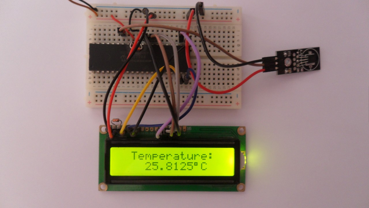
PIC18F4550 microcontroller with DS18B20 sensor and LCD circuit:
Project circuit schematic diagram is shown below.

(All grounded terminals are connected together)
The DS18B20 sensor has 3 pins (from left to right): GND, data and VCC (+5V). The data pin is connected to PIC18F4550 pin RB1.
The LCD screen is used to display the temperature value read by the DS18B20 sensor. It’s connected to PORTD pins with:
RS —> RD0
RW –> RD1
E —> RD2
D4 —> RD3
D5 —> RD4
D6 —> RD5
D7 —> RD6
In this example the PIC18F4550 microcontroller runs with its internal oscillator (@ 8MHz) and MCLR pin is configured as a digital input pin (configured in the software).
PIC18F4550 microcontroller with DS18B20 sensor and LCD C code:
The C code below is for CCS C compiler, it was tested with version 5.051.
Functions used in the code:
int1 ds18b20_start(): used to know if the DS18B20 sensor is correctly connected to the circuit, returns TRUE (1) if OK and FALSE (0) if error.
void ds18b20_write_bit(int1 value): writes (sends) 1 bit to the DS18B20 sensor, the bit is ‘value’ which may be 1 or 0.
void ds18b20_write_byte(int8 value): writes 1 byte (8 bits) to the DS18B20 sensor, this function is based on the previous function. This function writes LSB (Least Significant Bit) first.
int1 ds18b20_read_bit(void): reads 1 bit from the DS18B20 sensor, returns the read value (1 or 0).
int8 ds18b20_read_byte(void): reads 1 byte (8 bits) from the DS18B20 sensor, this function is based on the previous function. This function reads LSB first.
int1 ds18b20_read(int16 *raw_temp_value): reads the temperature raw data which is 16-bit long (two 8-bit registers), the data is stored in the variable raw_temp_value, returns TRUE if OK and FALSE if error.
1 2 3 4 5 6 7 8 9 10 11 12 13 14 15 16 17 18 19 20 21 22 23 24 25 26 27 28 29 30 31 32 33 34 35 36 37 38 39 40 41 42 43 44 45 46 47 48 49 50 51 52 53 54 55 56 57 58 59 60 61 62 63 64 65 66 67 68 69 70 71 72 73 74 75 76 77 78 79 80 81 82 83 84 85 86 87 88 89 90 91 92 93 94 95 96 97 98 99 100 101 102 103 104 105 106 107 108 109 110 111 112 113 114 115 116 117 118 119 120 121 122 123 124 125 126 127 128 129 130 131 132 133 134 135 136 137 138 139 140 141 142 143 | /* Interfacing PIC18F4550 with DS18B20 temperature sensor and LCD The measured temperature is displayed on 16x2 LCD connected to PORTD Internal oscillator used @ 8MHz C Code for CCS C compiler http://simple-circuit.com/ */ // LCD module connections #define LCD_RS_PIN PIN_D0 #define LCD_RW_PIN PIN_D1 #define LCD_ENABLE_PIN PIN_D2 #define LCD_DATA4 PIN_D3 #define LCD_DATA5 PIN_D4 #define LCD_DATA6 PIN_D5 #define LCD_DATA7 PIN_D6 // End LCD module connections #define DS18B20_PIN PIN_B1 // DS18B20 Data pin is connected to pin RB1 #include <18F4550.h> #fuses NOMCLR, INTRC_IO, NOWDT,NOPROTECT,NOLVP #use delay(clock = 8000000) #include <lcd.c> #use fast_io(B) int16 raw_temp; char *temp = "000.0000 C"; int1 ds18b20_start(){ output_low(DS18B20_PIN); // Send reset pulse to the DS18B20 sensor output_drive(DS18B20_PIN); // Configure DS18B20_PIN pin as output delay_us(500); // Wait 500 us output_float(DS18B20_PIN); // Configure DS18B20_PIN pin as input delay_us(100); //wait to read the DS18B20 sensor response if (!input(DS18B20_PIN)) { delay_us(400); // Wait 400 us return TRUE; // DS18B20 sensor is present } return FALSE; } void ds18b20_write_bit(int1 value){ output_low(DS18B20_PIN); output_drive(DS18B20_PIN); // Configure DS18B20_PIN pin as output delay_us(2); // Wait 2 us output_bit(DS18B20_PIN, value); delay_us(80); // Wait 80 us output_float(DS18B20_PIN); // Configure DS18B20_PIN pin as input delay_us(2); // Wait 2 us } void ds18b20_write_byte(int8 value){ int8 i; for(i = 0; i < 8; i++) ds18b20_write_bit(bit_test(value, i)); } int1 ds18b20_read_bit(void) { int1 value; output_low(DS18B20_PIN); output_drive(DS18B20_PIN); // Configure DS18B20_PIN pin as output delay_us(2); output_float(DS18B20_PIN); // Configure DS18B20_PIN pin as input delay_us(5); // Wait 5 us value = input(DS18B20_PIN); delay_us(100); // Wait 100 us return value; } int8 ds18b20_read_byte(void) { int8 i, value = 0; for(i = 0; i < 8; i++) shift_right(&value, 1, ds18b20_read_bit()); return value; } int1 ds18b20_read(int16 *raw_temp_value) { if (!ds18b20_start()) // Send start pulse return FALSE; ds18b20_write_byte(0xCC); // Send skip ROM command ds18b20_write_byte(0x44); // Send start conversion command while(ds18b20_read_byte() == 0); // Wait for conversion complete if (!ds18b20_start()) // Send start pulse return FALSE; // Return 0 if error ds18b20_write_byte(0xCC); // Send skip ROM command ds18b20_write_byte(0xBE); // Send read command *raw_temp_value = ds18b20_read_byte(); // Read temperature LSB byte and store it on raw_temp_value LSB byte *raw_temp_value |= (int16)(ds18b20_read_byte()) << 8; // Read temperature MSB byte and store it on raw_temp_value MSB byte return TRUE; // OK --> return 1 } void main(void) { setup_oscillator(OSC_8MHZ); // Set internal oscillator to 8MHz lcd_init(); // Initialize LCD module lcd_putc('\f'); // clear LCD command lcd_gotoxy(3, 1); // Go to column 3 row 1 lcd_putc("Temperature:"); temp[8] = 223; // Put degree symbol ( ° ) while (TRUE) { if(ds18b20_read(&raw_temp)) { if(raw_temp & 0x8000) { // If the temperature is negative temp[0] = '-'; // Put minus sign (-) raw_temp = ~raw_temp + 1; // Change temperature value to positive form } else { if((raw_temp >> 4) >= 100) // If the temperatue >= 100 °C temp[0] = '1'; // Put 1 of hundreds else // otherwise temp[0] = ' '; // put space ' ' } // Put the first two digits ( for tens and ones) temp[1] = ( (raw_temp >> 4) / 10 ) % 10 + 48; // Put tens digit temp[2] = (raw_temp >> 4) % 10 + 48; // Put ones digit // Put the 4 fraction digits (digits after the point) // Why 625: because we're working with 12-bit resolution (default resolution) temp[4] = ( (raw_temp & 0x0F) * 625) / 1000 + 48; // Put thousands digit temp[5] = (((raw_temp & 0x0F) * 625) / 100 ) % 10 + 48; // Put hundreds digit temp[6] = (((raw_temp & 0x0F) * 625) / 10 ) % 10 + 48; // Put tens digit temp[7] = ( (raw_temp & 0x0F) * 625) % 10 + 48; // Put ones digit lcd_gotoxy(4, 2); // Go to column 4 row 2 printf(lcd_putc, temp); //lcd_putc(temp); } else { lcd_gotoxy(4, 2); // Go to column 4 row 2 lcd_putc(" Error! "); } delay_ms(1000); // Wait 1 second } } // End of code |
Proteus simulation of the project is the one below:
PIC18F4550 + DS18B20 sensor + LCD Proteus simulation file download:
Download
Discover more from Simple Circuit
Subscribe to get the latest posts sent to your email.


