This post shows how to interface PIC18F46K22 microcontroller with SSD1306 OLED (128×64 pixel).
The SSD1306 is a monochrome display which means it has only one color (white, blue, yellow …).
This display communicates with the master device over I2C mode, SPI mode or 8-bit parallel mode.
This topic shows how to use the SSD1306 OLED in SPI mode.
The compiler used in this project is mikroElektronika mikroC PRO for PIC.
SPI: Serial Peripheral Interface.
I2C (or IIC): Inter-Integrated Circuit.
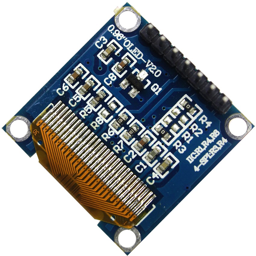
The SSD1306 OLED which I’m going to use in this project is shown below (back view), the default mode is SPI which can be changed to I2C by removing the resistors R3 and placing the resistors R1 & R8 (as written on the board). Note that resistance of R1 = R3 = R8 = 0 ohm.
To see how to use the SSD1306 OLED display module in I2C mode, visit this post:
PIC MCU with SSD1306 OLED – I2C Mode Example | mikroC Projects
Hardware Required:
- PIC18F46K22 microcontroller —-> datasheet
- SSD1306 OLED display
- 5V source
- Breadboard
- Jumper wires
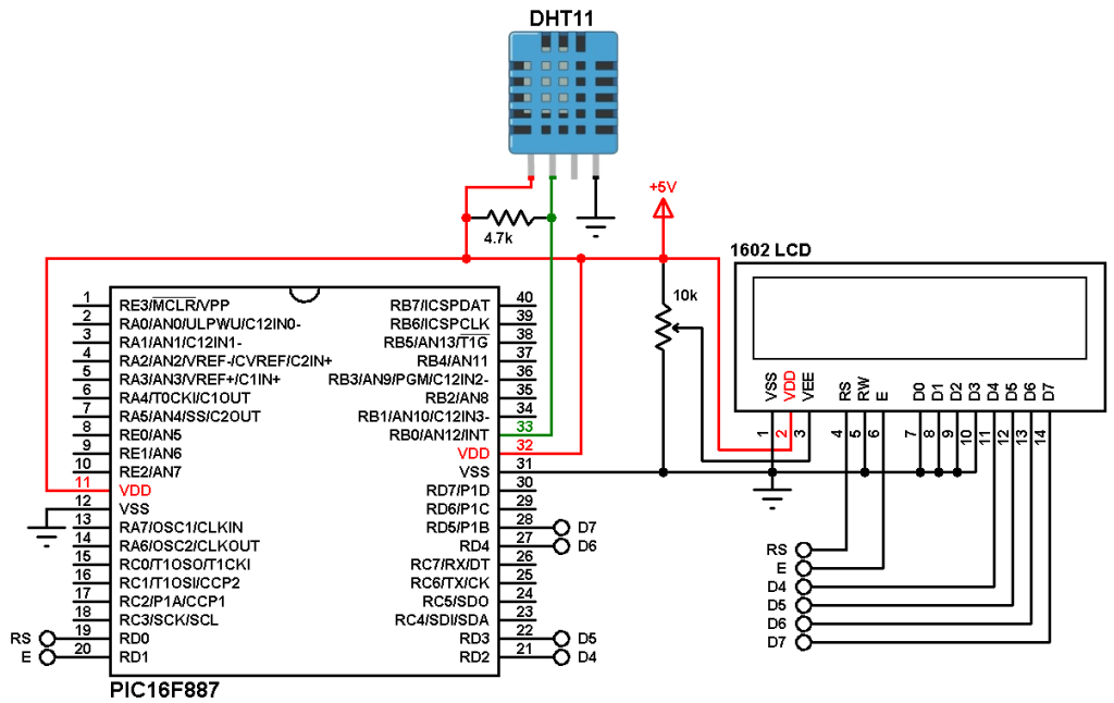
PIC18F46K22 with SSD1306 OLED display circuit (4-wire SPI mode):
Example circuit diagram is shown below.
The SSD1306 OLED display module shown in the circuit diagram has 7 pins (from left to right):
GND, VCC, SCK (serial clock), SDA (serial data), RES (reset), DC (or D/C: data/command) and CS (chip select).
The SSD1306 display board is supplied with 5V where GND is connected to circuit ground and VCC is connected to +5V.
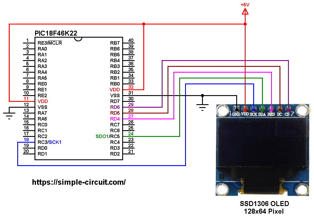
All the grounded terminals are connected together.
The PIC18F46K22 microcontroller has 2 hardware SPI modules (MSSP1 and MSSP2 modules).
In this project SPI1 module is used with SCK1 on pin RC3 (#18) and SDO1 (MOSI) on pin RC5 (#24). SCK1 and SDO1 pins of the PIC18F46K22 MCU are respectively connected to SCK and SDA pins of the SSD1306 OLED display module.
The other pins of the display module which are RES, DC and CS are respectively connected to PIC18F46K22 pins RD4 (#27), RD5 (#28) and RD6 (#29).
SCK: Serial Clock.
SDO: Serial Data-Out, synonym for MOSI.
MOSI: Master-Out Slave-In.
In this project the PIC18F46K22 microcontroller runs with its internal oscillator @ 16 MHz, MCLR pin is configured as an input pin.
PIC18F46K22 with SSD1306 OLED display C code (4-wire SPI mode):
The following C code is for mikroC PRO for PIC compiler, it was tested with version 7.6.0.
To be able to compile project C code with no error, 2 libraries are required:
The first library is a driver for the SSD1306 OLED display, its full name (with extension) is SSD1306.c, download link is below:
SSD1306 OLED display library for mikroC compiler
The second library is graphics library, its full name is GFX_Library.c, download link is the one below:
Graphics library for mikroC compiler
after the download of the 2 library files, add both of them to project folder.
In this example, the SSD1306 OLED display is connected to hardware SPI1 (MSSP1 module) of the PIC18F46K22 microcontroller. Hardware SPI2 module (MSSP2) or mikroC software SPI library (built-in) also can be used.
To use hardware SPI1 module the following line have to be defined (before #include “SSD1306.c”):
#define SSD1306_HARD_SPI1
To use mikroC software SPI library just define the following line:
#define SSD1306_SOFT_SPI
In software SPI we’ve to configure the pins used (MISO, MOSI and SCK) by mikroC software SPI library as shown in the help file.
Also the configuration should be initialized in the main code (always before initializing the display) with this line:
Soft_SPI_Init();
The clock frequency of the software SPI library is fixed to 20 kHz (slow!).
If the display module is connected to hardware SPI2 (MSSP2 module) then we’ve to define this line:
#define SSD1306_HARD_SPI2
and hardware SPI2 module must be initialized before the initialization of the SSD1306 OLED display (for example SPI2_Init();).
The SSD1306 OLED display library supports three types depending on screen size (number of pixels): 128×64, 128×32 and 96×16. The default one is 128×64.
If the display used is 128×32 then the line below has to be added before #include “SSD1306.c”:
#define SSD1306_128_32
and if the display used is 96×16 then use this definition:
#define SSD1306_96_16
Hints:
The 2 library files are included in the main code as shown below:
1 2 | #include "SSD1306.c" // include SSD1306 OLED display driver source code #include "GFX_Library.c" // include graphics library source code |
The line below allows us to use hardware SPI1 module as mentioned above:
1 2 | // use SSD1306 OLED display with mikroC hardware SPI1 module #define SSD1306_HARD_SPI1 |
Other required pins (RST, DC and CS) are defined as shown below:
1 2 3 4 5 6 7 | // define other pins: RST, DC and CS #define SSD1306_RST RD4_bit #define SSD1306_DC RD5_bit #define SSD1306_CS RD6_bit #define SSD1306_RST_DIR TRISD4_bit #define SSD1306_DC_DIR TRISD5_bit #define SSD1306_CS_DIR TRISD6_bit |
The display is initialized as shown below:
1 2 3 | // by default, we'll generate the high voltage from the 3.3v line internally! (neat!) // initialize the SSD1306 OLED display SSD1306_begin(SSD1306_SWITCHCAPVCC); |
Rest of code is described through comments.
Full mikroC code:
1 2 3 4 5 6 7 8 9 10 11 12 13 14 15 16 17 18 19 20 21 22 23 24 25 26 27 28 29 30 31 32 33 34 35 36 37 38 39 40 41 42 43 44 45 46 47 48 49 50 51 52 53 54 55 56 57 58 59 60 61 62 63 64 65 66 67 68 69 70 71 72 73 74 75 76 77 78 79 80 81 82 83 84 85 86 87 88 89 90 91 92 93 94 95 96 97 98 99 100 101 102 103 104 105 106 107 108 109 110 111 112 113 114 115 116 117 118 119 120 121 122 123 124 125 126 127 128 129 130 131 132 133 134 135 136 137 138 139 140 141 142 143 144 145 146 147 148 149 150 151 152 153 154 155 156 157 158 159 160 161 162 163 164 165 166 167 168 169 170 171 172 173 174 175 176 177 178 179 180 181 182 183 184 185 186 187 188 189 190 191 192 193 194 195 196 197 198 199 200 201 202 203 204 205 206 207 208 209 210 211 212 213 214 215 216 217 218 219 220 221 222 223 224 225 226 227 228 229 230 231 232 233 234 235 236 237 238 239 240 241 242 243 244 245 246 247 248 249 250 251 252 253 254 255 256 257 258 259 260 261 262 263 264 265 266 267 268 269 270 271 272 273 274 275 276 277 278 279 280 281 282 283 284 285 286 287 288 289 290 291 292 293 294 295 296 297 298 299 300 301 302 303 304 305 306 307 308 309 310 311 312 313 314 315 316 317 318 319 320 321 322 323 324 325 326 327 328 329 330 331 332 333 334 335 336 337 338 339 340 341 342 343 344 345 346 347 348 349 350 351 352 353 354 355 356 357 358 359 360 361 362 363 364 365 366 367 368 369 370 371 372 373 374 375 376 377 378 379 380 381 382 383 384 385 386 387 388 389 390 391 392 393 394 395 396 397 398 399 400 401 | /******************************************************************* Interfacing PIC18F46K22 MCU with SSD1306 OLED display (SPI mode). C Code for mikroC PRO for PIC compiler. Internal oscillator used @ 16MHz Configuration words: CONFIG1H = 0x0028 CONFIG2L = 0x0018 CONFIG2H = 0x003C CONFIG3H = 0x0037 CONFIG4L = 0x0081 CONFIG5L = 0x000F CONFIG5H = 0x00C0 CONFIG6L = 0x000F CONFIG6H = 0x00E0 CONFIG7L = 0x000F CONFIG7H = 0x0040 This is a free software with NO WARRANTY. http://simple-circuit.com/ ********************************************************************* This is an example for our Monochrome OLEDs based on SSD1306 drivers Pick one up today in the adafruit shop! ------> http://www.adafruit.com/category/63_98 This example is for a 128x64 size display using SPI to communicate 4 or 5 pins are required to interface Adafruit invests time and resources providing this open source code, please support Adafruit and open-source hardware by purchasing products from Adafruit! Written by Limor Fried/Ladyada for Adafruit Industries. BSD license, check license.txt for more information All text above, and the splash screen must be included in any redistribution ****************************************************************************/ // use SSD1306 OLED display with mikroC hardware SPI1 module #define SSD1306_HARD_SPI1 // define other pins: RST, DC and CS #define SSD1306_RST RD4_bit #define SSD1306_DC RD5_bit #define SSD1306_CS RD6_bit #define SSD1306_RST_DIR TRISD4_bit #define SSD1306_DC_DIR TRISD5_bit #define SSD1306_CS_DIR TRISD6_bit #include "SSD1306.c" // include SSD1306 OLED display driver source code #include "GFX_Library.c" // include graphics library source code #define NUMFLAKES 10 #define XPOS 0 #define YPOS 1 #define DELTAY 2 #define LOGO16_GLCD_HEIGHT 16 #define LOGO16_GLCD_WIDTH 16 const char logo16_glcd_bmp[] = { 0b00000000, 0b11000000, 0b00000001, 0b11000000, 0b00000001, 0b11000000, 0b00000011, 0b11100000, 0b11110011, 0b11100000, 0b11111110, 0b11111000, 0b01111110, 0b11111111, 0b00110011, 0b10011111, 0b00011111, 0b11111100, 0b00001101, 0b01110000, 0b00011011, 0b10100000, 0b00111111, 0b11100000, 0b00111111, 0b11110000, 0b01111100, 0b11110000, 0b01110000, 0b01110000, 0b00000000, 0b00110000 }; void testdrawbitmap(const uint8_t *bitmap, uint8_t w, uint8_t h) { static uint8_t icons[NUMFLAKES][3], f, x_pos, y_pos; // initialize for (f=0; f< NUMFLAKES; f++) { icons[f][XPOS] = rand(); icons[f][YPOS] = 0; icons[f][DELTAY] = (rand() % 5) + 1; } while (1) { uint8_t f; // draw each icon for (f=0; f< NUMFLAKES; f++) { x_pos = icons[f][XPOS]; y_pos = icons[f][YPOS]; display_drawBitmapV2(x_pos, y_pos, bitmap, w, h, WHITE); } display(); delay_ms(200); // then erase it + move it for (f=0; f< NUMFLAKES; f++) { x_pos = icons[f][XPOS]; y_pos = icons[f][YPOS]; display_drawBitmapV2(x_pos, y_pos, bitmap, w, h, BLACK); // move it icons[f][YPOS] += icons[f][DELTAY]; // if its gone, reinit if (icons[f][YPOS] > display_height) { icons[f][XPOS] = rand(); icons[f][YPOS] = 0; icons[f][DELTAY] = (rand() % 5) + 1; } } } } void testdrawchar(void) { uint8_t i; display_setTextSize(1); display_setTextColor(WHITE, WHITE); display_setCursor(0, 0); for (i=0; i < 170; i++) { if (i == '\n' || i == '\r') continue; display_putc(i); } display(); delay_ms(1); } void testdrawcircle(void) { uint16_t i; for (i=0; i<display_height; i+=2) { display_drawCircle(display_width/2, display_height/2, i, WHITE); display(); delay_ms(1); } } void testfillrect(void) { uint8_t color = 1; uint16_t i; for (i=0; i<display_height/2; i+=3) { // alternate colors display_fillRect(i, i, display_width-i*2, display_height-i*2, color%2); display(); delay_ms(1); color++; } } void testdrawtriangle(void) { uint16_t i; for (i=0; i<min(display_width,display_height)/2; i+=5) { display_drawTriangle(display_width/2, display_height/2-i, display_width/2-i, display_height/2+i, display_width/2+i, display_height/2+i, WHITE); display(); delay_ms(1); } } void testfilltriangle(void) { uint8_t color = WHITE; int16_t i; for (i =0 ; i < min(display_width,display_height)/2; i += 5) { display_fillTriangle(display_width/2, display_height/2-i, display_width/2-i, display_height/2+i, display_width/2+i, display_height/2+i, WHITE); if (color == WHITE) color = BLACK; else color = WHITE; display(); delay_ms(1); } } void testdrawroundrect(void) { uint16_t i; for (i=0; i<display_height/2-2; i+=2) { display_drawRoundRect(i, i, display_width-2*i, display_height-2*i, display_height/4, WHITE); display(); delay_ms(1); } } void testfillroundrect(void) { uint8_t color = WHITE; uint16_t i; for (i=0; i<display_height/2-2; i+=2) { display_fillRoundRect(i, i, display_width-2*i, display_height-2*i, display_height/4, color); if (color == WHITE) color = BLACK; else color = WHITE; display(); delay_ms(1); } } void testdrawrect(void) { uint16_t i; for (i=0; i<display_height/2; i+=2) { display_drawRect(i, i, display_width-2*i, display_height-2*i, WHITE); display(); delay_ms(1); } } void testdrawline() { int16_t i; for (i=0; i<display_width; i+=4) { display_drawLine(0, 0, i, display_height-1, WHITE); display(); delay_ms(1); } for (i=0; i<display_height; i+=4) { display_drawLine(0, 0, display_width-1, i, WHITE); display(); delay_ms(1); } delay_ms(250); display_clear(); for (i=0; i<display_width; i+=4) { display_drawLine(0, display_height-1, i, 0, WHITE); display(); delay_ms(1); } for (i=display_height-1; i>=0; i-=4) { display_drawLine(0, display_height-1, display_width-1, i, WHITE); display(); delay_ms(1); } delay_ms(250); display_clear(); for (i=display_width-1; i>=0; i-=4) { display_drawLine(display_width-1, display_height-1, i, 0, WHITE); display(); delay_ms(1); } for (i=display_height-1; i>=0; i-=4) { display_drawLine(display_width-1, display_height-1, 0, i, WHITE); display(); delay_ms(1); } delay_ms(250); display_clear(); for (i=0; i<display_height; i+=4) { display_drawLine(display_width-1, 0, 0, i, WHITE); display(); delay_ms(1); } for (i=0; i<display_width; i+=4) { display_drawLine(display_width-1, 0, i, display_height-1, WHITE); display(); delay_ms(1); } delay_ms(250); } void testscrolltext(void) { display_setTextSize(2); display_setTextColor(WHITE, WHITE); display_setCursor(10,0); display_clear(); display_puts("scroll\r\n"); display(); delay_ms(1); display_startscrollright(0x00, 0x0F); delay_ms(2000); display_stopscroll(); delay_ms(1000); display_startscrollleft(0x00, 0x0F); delay_ms(2000); display_stopscroll(); delay_ms(1000); display_startscrolldiagright(0x00, 0x07); delay_ms(2000); display_startscrolldiagleft(0x00, 0x07); delay_ms(2000); display_stopscroll(); } // main function void main() { OSCCON = 0x70; // set internal oscillator to 16MHz ANSELC = 0; // configure all PORTC pins as digital ANSELD = 0; // configure all PORTD pins as digital SPI1_Init(); // initialize the SPI1 module with default settings // by default, we'll generate the high voltage from the 3.3v line internally! (neat!) // initialize the SSD1306 OLED display SSD1306_begin(SSD1306_SWITCHCAPVCC); // init done // show image buffer on the display hardware. // Since the buffer is intialized with an Adafruit splashscreen // internally, this will display the splashscreen. display(); delay_ms(2000); // clear the buffer. display_clear(); // draw a single pixel display_drawPixel(10, 10, WHITE); // Show the display buffer on the hardware. // NOTE: You _must_ call display after making any drawing commands // to make them visible on the display hardware! display(); delay_ms(2000); display_clear(); // draw many lines testdrawline(); display(); delay_ms(2000); display_clear(); // draw rectangles testdrawrect(); display(); delay_ms(2000); display_clear(); // draw multiple rectangles testfillrect(); display(); delay_ms(2000); display_clear(); // draw mulitple circles testdrawcircle(); display(); delay_ms(2000); display_clear(); // draw a white circle, 10 pixel radius display_fillCircle(display_width/2, display_height/2, 10, WHITE); display(); delay_ms(2000); display_clear(); testdrawroundrect(); delay_ms(2000); display_clear(); testfillroundrect(); delay_ms(2000); display_clear(); testdrawtriangle(); delay_ms(2000); display_clear(); testfilltriangle(); delay_ms(2000); display_clear(); // draw the first ~12 characters in the font testdrawchar(); display(); delay_ms(2000); display_clear(); // draw scrolling text testscrolltext(); delay_ms(2000); display_clear(); // text display tests display_setTextSize(1); display_setTextColor(WHITE, BLACK); display_setCursor(0, 0); display_printf("Hello, world!\r\n"); display_setTextColor(BLACK, WHITE); // 'inverted' text display_printf("%4.2f\r\n", 3.141592); display_setTextSize(2); display_setTextColor(WHITE, BLACK); display_printf("0x%LX\r\n", 0xDEADBEEF); display(); delay_ms(2000); display_clear(); // miniature bitmap display display_drawBitmapV2(30, 16, logo16_glcd_bmp, 16, 16, WHITE); display(); delay_ms(1); // invert the display display_invert(true); delay_ms(1000); display_invert(false); delay_ms(1000); display_clear(); // draw a bitmap icon and 'animate' movement testdrawbitmap(logo16_glcd_bmp, LOGO16_GLCD_HEIGHT, LOGO16_GLCD_WIDTH); } // end of code. |
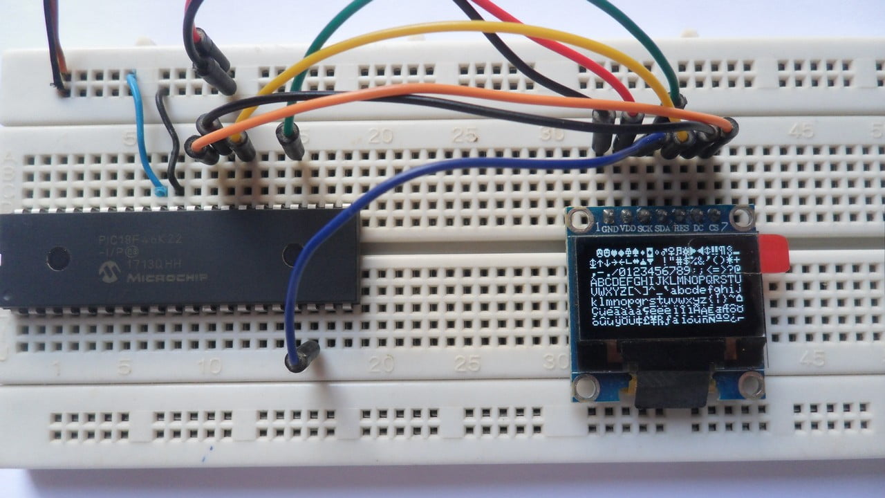
Protoboard hardware circuit:
Proteus simulation:
This example works with Proteus simulation software since it (Proteus) contains the SSD1306 OLED library. The video below shows the simulation result:
Proteus simulation file download link is below, use version 8.6 or higher to open it:
PIC18F46K22 + SSD1306 OLED SPI mode
Discover more from Simple Circuit
Subscribe to get the latest posts sent to your email.
can we use this code with pic18f452
hi sir,
I am try with (pic18f46k22) pic controller with OLED 1306 display with SPI base. and using library with mplab-x.but display not showing any this. Not working. Help me.
Regarding
Ajay
Hello Ajay, I have I2C bus protocol library , not SPI library bus for your dad display !! I wrote it for MicroC compiler but I suppose it will compatible for your mplab system. If you want it I could share it tomorrow morning. Ok?
Hello Ajay, I have I2C bus protocol library , not SPI library bus for your ssd display !! I wrote it for MicroC compiler but I suppose it will compatible for your mplab system. I’m using it for 18F26k22mcu but it is similar to your. If you want it I could share it tomorrow morning. Ok?
Hello i downloded the ssd1306 i2C library (unless reset pin), in follow link:
http://www.mediafire.com/folder/34053l8o3xct1/OLED_LIbrary_18f26k22
Video of Problem link:
http://www.mediafire.com/file/rnqx5rsab9ajc0v/VU-Meter-simulation.mp4/file
there’s ssd1306.c library (ssd1306 4pin unless reset) and the main. Library work fine but the main i slorly to drive ssd1306. In my main there’s a VU-Meter simulation but the vu-meter needle is slow to move. (the mcu pik has a clock frequency of 16mhz x 4PLL = 64mhz).
Cound, some one, help me to speed up your code please ? probabily the problem is SSD1306_ClearDisplay() function inside FOR cicle.
I need to store and restore only the background pixels that are erased from the needle drawing of the vu-meter.
I’ll wait your reply, thank you.
Leonardo