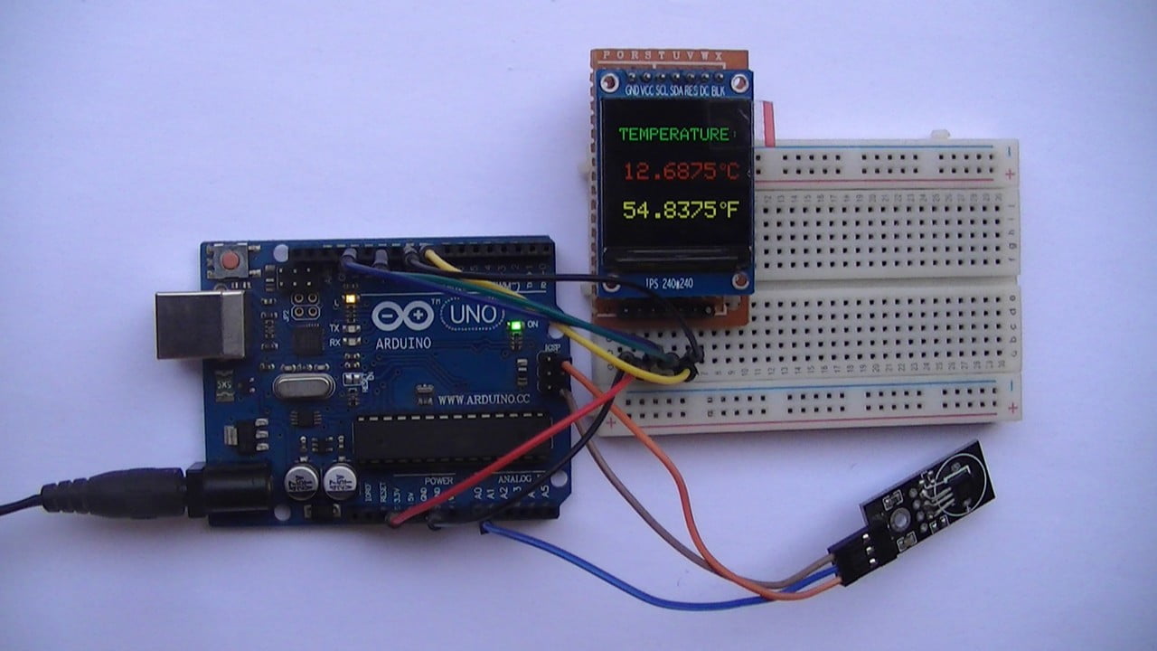
This tutorial shows how to implement a simple digital thermometer using Arduino UNO board and DS18B20 temperature sensor.
The Arduino microcontroller (for example ATmega328P) reads temperature value from the DS18B20 sensor and prints it (in °C and °F) on ST7789 TFT display.
The ST7789 TFT module contains a display controller with the same name: ST7789. It’s a color display that uses SPI interface protocol and requires 3, 4 or 5 control pins, it’s low cost and easy to use.
The ST7789 TFT is an IPS display, it comes in different sizes (1.3″, 1.54″ …) but all of them should have the same resolution of 240×240 pixel (some may come with 320×240 pixel), this means it has 57600 pixels. This module works with 3.3V only and it doesn’t support 5V (not 5V tolerant).
TFT: Thin-Film Transistor.
SPI: Serial Peripheral Interface.
IPS: In-Plane Switching.
HVAC: Heating, Ventilation and Air Conditioning.
To see how to interface Arduino with ST7789 TFT display, visit this post:
Interfacing Arduino with ST7789 TFT Display – Graphics Test Example
About the DS18B20 sensor (from datasheet):
The DS18B20 digital thermometer from Maxim Integrated provides 9-bit to 12-bit Celsius temperature measurements and has an alarm function with nonvolatile user-programmable upper and lower trigger points. The DS18B20 communicates over a 1-Wire bus that by definition requires only one data line (and ground) for communication with a central microprocessor. In addition, the DS18B20 can derive power directly from the data line (“parasite power”), eliminating the need for an external power supply. Each DS18B20 has a unique 64-bit serial code, which allows multiple DS18B20s to function on the same 1-Wire bus. Thus, it is simple to use one microprocessor to control many DS18B20s distributed over a large area. Applications that can benefit from this feature include HVAC environmental controls, temperature monitoring systems inside buildings, equipment, or machinery, and process monitoring and control systems.
Benefits and features:
- Unique 1-Wire® interface requires only one port pin for communication,
- Reduce component count with integrated temperature sensor and EEPROM,
- Measures temperatures from -55°C to +125°C (-67°F to +257°F),
- ±0.5°C Accuracy from -10°C to +85°C,
- Programmable resolution from 9 bits to 12 bits,
- No external components required,
- Parasitic power mode requires only 2 pins for operation (DQ and GND),
- Simplifies distributed temperature-sensing applications with multidrop capability,
- Each device has a unique 64-bit serial code stored in on-board ROM,
- Flexible user-definable nonvolatile (NV) alarm settings with alarm search command identifies devices with temperatures outside programmed limits,
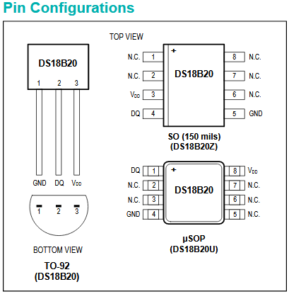
- Available in 8-pin SO (150 mils), 8-pin μSOP, and 3-pin TO-92 packages.
Hardware Required:
- Arduino uno board
- ST7789 TFT display module (1.3″, 1.54″ …)
- DS18B20 temperature sensor —-> datasheet
- 4 x 3.3k ohm resistor (+1 if the display module has CS pin)
- 4 x 2.2k ohm resistor (+1 if the display module has CS pin)
- 4.7k ohm resistor
- Breadboard
- Jumper wires
Arduino with DS18B20 sensor and ST7789 TFT circuit:
The image below shows project circuit diagram.
The DS18B20 sensor has 3 pins (from right to left): VCC (or VDD), data (DQ) and GND where:
VCC (VDD): sensor power supply pin, connected to Arduino 5V pin,
data (DQ) pin: connected to Arduino analog pin 0 (A0) and
GND: connected to Arduino GND pin.
A pull-up resistor of 4.7k ohm is required because the DS18B20 output is open drain.
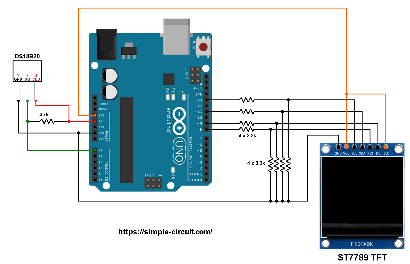
The ST7789 display module shown in project circuit diagram has 7 pins: (from right to left): GND (ground), VCC, SCL (serial clock), SDA (serial data), RES (reset), DC (or D/C: data/command) and BLK (back light).
Connecting the BLK pin is optional. The back light turns off when the BLK pin connected to the ground (GND).
As mentioned above, the ST7789 TFT display controller works with 3.3V only (power supply and control lines). The display module is supplied with 3.3V (between VCC and GND) which comes from the Arduino board.
All Arduino UNO board output pins are 5V, connecting a 5V pin to the ST7789 TFT display may damage its controller.
To connect the Arduino to the display module, I used voltage divider for each line which means there are 4 voltage dividers. Each voltage divider consists of 2.2k and 3.3k resistors, this drops the 5V into 3V which is sufficient.
If the display module has a CS pin (Chip Select) then it should be connected to Arduino digital pin 10 through another voltage divider.
So, the ST7789 TFT display is connected to the Arduino board as follows (each one through voltage divider):
RST pin is connected to Arduino digital pin 8,
DC pin is connected to Arduino digital pin 9,
SDA pin is connected to Arduino digital pin 11,
SCL pin is connected to Arduino digital pin 13.
Other pins are connected as follows:
VCC pin is connected to Arduino 3V3 pin,
GND pin is connected to Arduino GND pin,
BL (LED) pin is connected to Arduino 3V3 pin (optional).
Arduino with DS18B20 sensor and ST7789 TFT code:
The following Arduino code requires 2 libraries from Adafruit Industries:
The first library is a driver for the ST7789 TFT display which can be installed from Arduino IDE library manager (Sketch —> Include Library —> Manage Libraries …, in the search box write “st7789” and install the one from Adafruit).
The second library is Adafruit graphics library which can be installed also from Arduino IDE library manager.
The 2 libraries can be installed manually, first download them from the following 2 links:
Adafruit ST7789 TFT library —-> direct link
Adafruit graphics library —-> direct link
After the download, go to Arduino IDE —> Sketch —> Include Library —> Add .ZIP Library … and browse for the .zip file (previously downloaded).
The same thing for other library file.
Hints:
The libraries are included in the main code as follows:
1 2 | #include <Adafruit_GFX.h> // Adafruit core graphics library #include <Adafruit_ST7789.h> // Adafruit hardware-specific library for ST7789 |
The ST7789 TFT module pins (CS, RST and DC) connections are defined as shown below (even the display module has no CS pin but its definition is required by the Adafruit ST7789 library):
1 2 3 4 | // ST7789 TFT module connections #define TFT_CS 10 // define chip select pin #define TFT_DC 9 // define data/command pin #define TFT_RST 8 // define reset pin, or set to -1 and connect to Arduino RESET pin |
The other display pins (SDA and SCL) are connected to Arduino hardware SPI module pins (digital pin 11 and digital pin 13 respectively for MOSI and SCLK).
The Adafruit ST7789 library is initialized with this line:
1 | Adafruit_ST7789 tft = Adafruit_ST7789(TFT_CS, TFT_DC, TFT_RST); |
And the TFT display is initialized using the following command:
1 2 3 | // initialize the ST7789 display (240x240 pixel) // if the display has CS pin try with SPI_MODE0 tft.init(240, 240, SPI_MODE2); |
The DS18B20 sensor data pin is connected to Arduino analog pin 0 (A0), it’s defined in the code as:
1 2 | // define DS18B20 data pin #define DS18B20_PIN A0 |
Functions used in the code:
bool ds18b20_start(): used to know if the DS18B20 sensor is correctly connected to the circuit, returns 1 if OK and 0 if error.
ds18b20_write_bit(bool value): writes (sends) 1 bit to the DS18B20 sensor, the bit is ‘value‘ which may be 1 or 0.
ds18b20_write_byte(byte value): writes 1 byte (8 bits) to the DS18B20 sensor, this function is based on the previous function. This function writes LSB first.
bool ds18b20_read_bit(void): reads 1 bit from the DS18B20 sensor, returns the read value (1 or 0).
byte ds18b20_read_byte(void): reads 1 byte from the DS18B20 sensor, this function is based on the previous function. This function reads LSB first.
bool ds18b20_read(int *raw_temp_value): reads the temperature raw data which is 16-bit long (two 8-bit registers), the data is stored in the variable raw_temp_value, returns 1 if OK and 0 if error.
The variable raw_temp_value, is signed 2-byte number which is actual temperature value (in °C) multiplied by 16 (why 16? —> because we’re working with 12-bit resolution).
For example if the returned valued equals to 209 means actual temperature is equal to 209/16 = 13.0625 °C.
To get the value of temperature in degrees Fahrenheit (°F), I used the function below:
1 | int32_t f_temp = (int32_t)c_temp * 90/5 + 5120; // 5120 = 32 x 16 x 10 |
This function is just from the common one: °F = °C x 9/5 + 32.
Since the temperature in °C is multiplied by 16 the 32 also needs to be multiplied by 16.
To get the °F temperature with no floating number, I multiplied every thing by 10.
This function gives the actual value of the temperature in °F multiplied by 160 (actual °F = f_temp/160).
Since the DS18B20 sensor is used with 12-bit resolution, we get the temperature in °C as shown below (example):
1 | sprintf(c_buffer, " %02u.%04u", c_temp/16, (c_temp & 0x0F) * 625); |
Again, why 16 and 625? —> Because we are working with 12-bit resolution (increment step = 0.0625).
The resolution of this thermometer is 0.0625°C (0.1125°F).
If the Arduino can’t connect the DS18B20 sensor due to for example, bad connection, the display will show “Error”.
Full Arduino code:
1 2 3 4 5 6 7 8 9 10 11 12 13 14 15 16 17 18 19 20 21 22 23 24 25 26 27 28 29 30 31 32 33 34 35 36 37 38 39 40 41 42 43 44 45 46 47 48 49 50 51 52 53 54 55 56 57 58 59 60 61 62 63 64 65 66 67 68 69 70 71 72 73 74 75 76 77 78 79 80 81 82 83 84 85 86 87 88 89 90 91 92 93 94 95 96 97 98 99 100 101 102 103 104 105 106 107 108 109 110 111 112 113 114 115 116 117 118 119 120 121 122 123 124 125 126 127 128 129 130 131 132 133 134 135 136 137 138 139 140 141 142 143 144 145 146 147 148 149 150 151 152 153 154 155 156 157 158 159 160 161 162 163 164 165 166 167 168 169 170 171 172 173 174 175 176 177 178 179 180 181 182 183 184 185 186 187 | /*********************************************************************** * * Interfacing Arduino with DS18B20 digital temperature sensor and * ST7789 TFT display (240x240 pixel). * This is a free software with NO WARRANTY. * http://simple-circuit.com/ * ***********************************************************************/ #include <Adafruit_GFX.h> // Adafruit core graphics library #include <Adafruit_ST7789.h> // Adafruit hardware-specific library for ST7789 // ST7789 TFT module connections #define TFT_CS 10 // define chip select pin #define TFT_DC 9 // define data/command pin #define TFT_RST 8 // define reset pin, or set to -1 and connect to Arduino RESET pin // initialize Adafruit ST7789 TFT library with hardware SPI module // MOSI(SDA) ---> Arduino digital pin 11 // SCK (SCL) ---> Arduino digital pin 13 Adafruit_ST7789 tft = Adafruit_ST7789(TFT_CS, TFT_DC, TFT_RST); // define DS18B20 data pin #define DS18B20_PIN A0 void setup(void) { // initialize the ST7789 display (240x240 pixel) // if the display has CS pin try with SPI_MODE0 tft.init(240, 240, SPI_MODE2); // if the screen is flipped, remove this command tft.setRotation(2); // fill the screen with black color tft.fillScreen(ST77XX_BLACK); tft.setTextWrap(false); // turn off text wrap option tft.setTextColor(ST77XX_GREEN, ST77XX_BLACK); // set text color to green and black background tft.setTextSize(3); // text size = 3 tft.setCursor(17, 41); // move cursor to position (15, 27) pixel tft.print("TEMPERATURE:"); tft.setTextSize(4); // text size = 4 } // variables int c_temp; char c_buffer[9], f_buffer[9]; // main loop void loop() { delay(1000); // wait a second // get temperature in °C ( actual temperature in °C = c_temp/16) if( ds18b20_read(&c_temp) ) { // read from DS18B20 sensor OK // calculate temperature in °F (actual temperature in °F = f_temp/160) // °F = °C x 9/5 + 32 int32_t f_temp = (int32_t)c_temp * 90/5 + 5120; // 5120 = 32 x 16 x 10 if(c_temp < 0) { // if temperature < 0 °C c_temp = abs(c_temp); // absolute value sprintf(c_buffer, "-%02u.%04u", c_temp/16, (c_temp & 0x0F) * 625); } else { if (c_temp/16 >= 100) // if temperature >= 100.0 °C sprintf(c_buffer, "%03u.%04u", c_temp/16, (c_temp & 0x0F) * 625); else sprintf(c_buffer, " %02u.%04u", c_temp/16, (c_temp & 0x0F) * 625); } if(f_temp < 0) { // if temperature < 0 °F f_temp = abs(f_temp); // absolute value sprintf(f_buffer, "-%02u.%04u", (uint16_t)f_temp/160, (uint16_t)(f_temp*1000/16 % 10000)); } else { if (f_temp/160 >= 100) // if temperature >= 100.0 °F sprintf(f_buffer, "%03u.%04u", (uint16_t)f_temp/160, (uint16_t)(f_temp*1000/16 % 10000)); else sprintf(f_buffer, " %02u.%04u", (uint16_t)f_temp/160, (uint16_t)(f_temp*1000/16 % 10000)); } tft.setTextColor(ST77XX_RED, ST77XX_BLACK); // set text color to red and black background tft.setCursor(0, 102); tft.print(c_buffer); tft.drawCircle(201, 108, 4, ST77XX_RED); // print degree symbol ( ° ) tft.drawCircle(201, 108, 5, ST77XX_RED); tft.setCursor(210, 102); tft.print("C"); tft.setTextColor(ST77XX_YELLOW, ST77XX_BLACK); // set text color to yellow and black background tft.setCursor(0, 170); tft.print(f_buffer); tft.drawCircle(201, 176, 4, ST77XX_YELLOW); // print degree symbol ( ° ) tft.drawCircle(201, 176, 5, ST77XX_YELLOW); tft.setCursor(210, 170); tft.print("F"); } else { // read from DS18B20 sensor ERROR! tft.setTextColor(ST77XX_WHITE, ST77XX_BLACK); // set text color to red and black background tft.setCursor(0, 102); tft.print(" Error "); tft.fillRect(0, 170, tft.width(), 28, ST77XX_BLACK); } } bool ds18b20_start() { bool ret = 0; digitalWrite(DS18B20_PIN, LOW); // send reset pulse to the DS18B20 sensor pinMode(DS18B20_PIN, OUTPUT); delayMicroseconds(500); // wait 500 us pinMode(DS18B20_PIN, INPUT); delayMicroseconds(100); // wait to read the DS18B20 sensor response if (!digitalRead(DS18B20_PIN)) { ret = 1; // DS18B20 sensor is present delayMicroseconds(400); // wait 400 us } return(ret); } void ds18b20_write_bit(bool value) { digitalWrite(DS18B20_PIN, LOW); pinMode(DS18B20_PIN, OUTPUT); delayMicroseconds(2); digitalWrite(DS18B20_PIN, value); delayMicroseconds(80); pinMode(DS18B20_PIN, INPUT); delayMicroseconds(2); } void ds18b20_write_byte(byte value) { byte i; for(i = 0; i < 8; i++) ds18b20_write_bit(bitRead(value, i)); } bool ds18b20_read_bit(void) { bool value; digitalWrite(DS18B20_PIN, LOW); pinMode(DS18B20_PIN, OUTPUT); delayMicroseconds(2); pinMode(DS18B20_PIN, INPUT); delayMicroseconds(5); value = digitalRead(DS18B20_PIN); delayMicroseconds(100); return value; } byte ds18b20_read_byte(void) { byte i, value; for(i = 0; i < 8; i++) bitWrite(value, i, ds18b20_read_bit()); return value; } bool ds18b20_read(int *raw_temp_value) { if (!ds18b20_start()) // send start pulse return(0); ds18b20_write_byte(0xCC); // send skip ROM command ds18b20_write_byte(0x44); // send start conversion command while(ds18b20_read_byte() == 0); // wait for conversion complete if (!ds18b20_start()) // send start pulse return(0); // return 0 if error ds18b20_write_byte(0xCC); // send skip ROM command ds18b20_write_byte(0xBE); // send read command // read temperature LSB byte and store it on raw_temp_value LSB byte *raw_temp_value = ds18b20_read_byte(); // read temperature MSB byte and store it on raw_temp_value MSB byte *raw_temp_value |= (unsigned int)(ds18b20_read_byte() << 8); return(1); // OK --> return 1 } // end of code. |
Discover more from Simple Circuit
Subscribe to get the latest posts sent to your email.


Thank you a billion for your code. I have a different TFT, an ILI9163C. It doesn’t work with the Onewire/Dallastemperature libraries, as long as the TFT is initialized, the libraries fail to read the sensor.
I scoured the internet. I tried EVERY DS18B20 library there was. I tried editing the TFT library. I tried using its sleep modes. I tried changing GPIO pins, resistors. Nothing worked. -127.000, every single time.
Until I found your code, on this page. It was the only one that worked, and also the only one that didn’t use any library, not even Onewire.h.
I improved it – edited the readbyte command from i<8 to i<12 to read the full 12bit resolution:
uint16_t ds18b20_read_byte(void)
{
byte i;
uint16_t value=0;
for(i = 0; i < 12 ; i++)
bitWrite(value, i, ds18b20_read_bit());
//terminal.print(value);
return value;
}
And now I can display it on my TFT without issue. Thank you so much for your code.