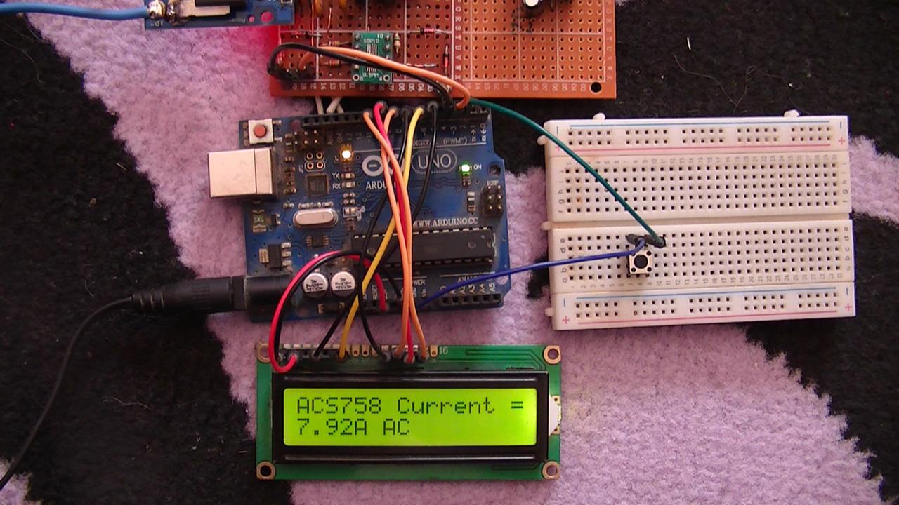
This post shows how to measure AC & DC currents using Arduino uno board and ACS758 hall effect current sensor with Ture RMS/average calculations.
A 1602 LCD connected to the Arduino board is used to display current values, the Arduino also sends the same values to the Laptop which can be viewed using serial monitor.
A pushbutton connected to the Arduino board is used to choose between AC and DC currents.
Hints:
No warranty is provided with this project, so do it at your own risk!
A part of project circuit may be subjected to high voltage which is very harmful to human body, so be-careful!
Abbreviations:
AC: Alternating Current
DC: Direct Current
TRMS: True Root Mean Square
ADC: Analog-to-Digital Converter
CT: Current Transformer
LDO Regulator: Low Dropout Regulator
PCB: Printed Circuit Board
DIY: Do It Yourself
About ACS758 current sensor:
The ACS758 family from Allegro™ is an integrated circuit (IC) which is specifically designed for current measurement with frequency upto 120kHz. It’s a hall-effect-based current sensor with 100µΩ current conductor. This device generates a voltage that is proportional to the current passing through it where the generated voltage is galvanically isolated from the passing current. This means at all times, high power circuit is isolated from low power circuit.
The ACS758 family consists of many versions with different current ratings: 50A, 100A, 150A and 200A. Some versions are bidirectional sensors and the others are unidirectional. Bidirectional means that the sensor can be used to measure current flow in both directions, they are most used with AC loads (it may be used also with DC loads). Unidirectional means the sensor can sense current flow in one direction only, this type is suitable for DC loads.
In this project I’m going to use bidirectional sensor with rated DC current of 200A, its full name is: ACS758ECB-200B. Since this device is bidirectional, it allows us to measure AC and DC currents with typical sensitivity of 10mV/A.
However, other ACS758 versions may also be used in this project, such as ACS758ECB-50B which has a typical sensitivity of 40mV/A.
ACS770 is a newer version of hall-effect based current sensors, it’s recommended by the manufacturer to use it instead of the ACS758!
When the ACS758ECB-200B is powered by single supply source with 5V and when the primary current is zero, then the output of the device is 2.5V (it’s just VCC/2), this voltage called: quiescent output voltage ( VIOUT(Q) ).
When a dual supply is used with ±2.5V the quiescent output voltage should be zero with respect to circuit ground.
With a supply of 5V (single or dual) the typical device sensitivity is 10mV/A. The sensitivity as defined in device datasheet is the change in device output in response to a 1 A change through the primary conductor. For example when a single supply is used and with primary current of 5 Amps then the device output is: VIOUT(Q) + 5 x 10mV = 2.5 + 0.05 = 2.550V.
Measure AC & DC Current with Arduino and ACS758 Sensor Circuit:
Project circuit diagram is shown below (click on the image for better view).
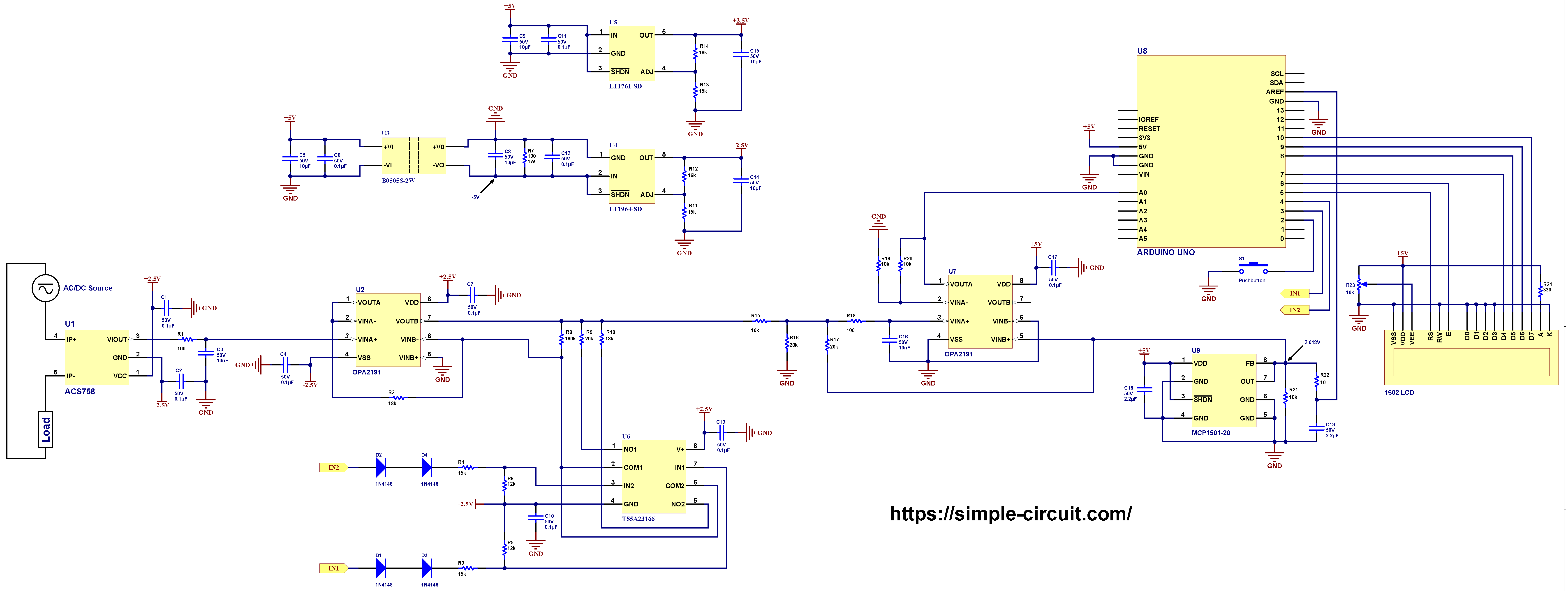
Note that in the circuit there is 1 ground only which is the same as Arduino board ground (GND).
The Arduino uno board is represented by U8.
For circuit resistors, a low tolerance resistors should be used, let’s say 1% or lower, lower tolerance yields better accuracy!
As shown in circuit schematic, the ACS758 current sensor is connected between the AC/DC source and the load. Instead of the ACS758 other similar devices may also be used, for example ACS770.
The voltage source may be AC or DC according to the connected load.
Hardware required:
This is a summary of circuit required parts (circuit schematic diagram may contain some component parameters not mentioned below).
- Arduino Uno or equivalent board such as Arduino Nano —> Board details —> ATmega328P datasheet
- ACS758 Hall-effect current sensor (U1) —> details
- 2 x OPA2191 op amp (U2, U7) —> details
- MCP1501-20 buffered voltage reference (U9) —> details
- TS5A23166 dual analog switch (U6) —> details
- LT1761-SD LDO regulator (U5) —> details
- LT1964-SD LDO negative regulator (U4) —> details
- B0505S-2W isolated DC-DC converter (U3)
- 1602 LCD screen
- 4 x 1N4184 diode (D1, D2, D3, D4)
- 180k resistor (R8)
- 3 x 20k resistor (R9, R16, R17)
- 2 x 18k resistor (R2, R10)
- 2 x 16k resistor (R5, R6)
- 4 x 15k resistor (R3, R4, R11, R13)
- 2 x 12k resistor (R5, R6)
- 4 x 10k resistor (R15, R19, R20, R21)
- 330 Ohm resistor (R24)
- 3 x 100 Ohm resistor (R1, R7, R18)
- 10 Ohm resistor (R22)
- 10k variable resistor (R23)
- 5 x 10 µF capacitor (C5, C8, C9, C14, C15)
- 2 x 2.2 µF capacitor (C18, C19)
- 10 x 0.1 µF capacitor (C1, C2, C4, C6, C7, C10, C11, C12, C13, C17)
- 2 x 10 nF capacitor (C3, C16)
- Pushbutton (S1)
- Breadboard
- Jumper wires
Circuit description:
The ACS758 current sensor is noted in the circuit schematic above as U1. It is supplied with bipolar source of ±2.5V. I used a bipolar power supply in order to easily amplify the ACS758 sensor output signal using operational amplifier circuit U2.
At rated current of +200A the voltage output of the ACS758 sensor is +2V and at current of -200A the output voltage is -2V (always with respect to circuit GND).
The output of the ACS758 is connected to a RC filter (R1 and C3) which removes any high frequency noise and then connected to OPA2191 operational amplifier U2.
The OPA2191 from Texas Instruments contains 2 independent op amps in one package. The first op amp is used as a voltage follower in order to properly buffer the ACS758 sensor output voltage.
The output of the voltage follower is connected to another op amp circuit which mainly consists of the second op amp of OPA2191 U2. This amplifier circuit has variable gain that can be digitally controlled by the Arduino board, the available gains are: 10, 1 and 0.5.
The Arduino automatically sets the gain of the amplifier, let’s say, when the output signal voltage of the ACS758 is very low then the gain should be 10, and when the output signal voltage is high the gain should be 0.5.
To easily control the amplifier gain I used TS5A23166 analog switch from Texas Instruments. This analog switch has an ON resistance of 0.9 Ohm which can be ignored when it is compared with 20k or 18k. A single chip of the TS5A23166 consists of two analog switches.
The first switch is closed (NO1 is connected to COM1) by sending a logic high to IN1 pin, and the second switch is closed (NO2 is connected to COM2) by sending a logic high to IN2 pin.
The digital control signals IN1 and IN2 are sent from pins 3 and 4 of the Arduino uno board, respectively.
With the two switches open, the gain of the inverting amplifier is equal to: 180k/18k = 10. When switch S1 closed the gain becomes: (180k // 20k)/18k = 18k/18k = 1. If both switches are closed then the gain is: (180k // 20k // 18k)/18k = 9k/18k = 0.5 .
ACS758 current sensor (U1), OPA2191 op amp (U2) and TS5A23166 (U6) are supplied with bipolar power supply with +2.5V and -2.5V. A bipolar supply allows me to easily amplify or attenuate the output voltage of the ACS758 current sensor using the op amp circuit described above.
I used LT1761-SD LDO regulator (U5) from Analog Devices to get approximately +2.5V, the input voltage of this regulator is 5V and it comes from the Arduino board, I chose R13 and R14 (connected to ADJ pin) respectively with values 15k and 16k to get an output of +2.5V (voltage output equation in LT1761 datasheet).
In the other hand, I used LT1964-SD LDO negative regulator (U4) also from Analog Devices to get approximately -2.5V, the input voltage of this regulator is -5V. I chose R11 and R12 (connected to ADJ pin) respectively with values 15k and 16k to get an output of -2.5V (voltage output equation in LT1964 datasheet).
However, to get -5V I used B0505S-2W isolated DC/DC converter (U3). The input as well as the output of this small module is 5V, with the input isolated from the output.
By connecting B0505S-2W output positive pin to circuit GND we get -5V on its negative pin (with respect to circuit GND). The negative voltage is then used to feed the LT1964-SD regulator.
The B0505S-2W input supply (5V) is from the Arduino board.
Since we are working with alternating current (& DC positive and negative currents) then a part of ACS758 sensor output signal waveform may be negative. The Arduino ADC module can’t read analog negative voltages and we need to shift all the waveform to the positive side, this means we have to add a dc offset to the signal produced by the OPA2191 (U2) without affecting the gain again.
For that I used another amplifier circuit which firstly filters the signal and secondly adds a dc offset of 1.024V. The main component is another OPA2191 (U7) where just 1 op amp is used. It is supplied with 5V from the Arduino board (pin 8 of U7 is connected to Arduino 5V pin, and pin 4 of U7 is connected to any of Arduino GND pins).
This circuit has a gain of 1 and dc offset of 1.024V.
The low pass filter removes any high frequency harmonics and other noise. The cutoff frequency can be calculated as follows:
f = 1/(2 x π x R x C) = 3.12KHz
Where: R = R15 // R16 // R17 + R18 = 5.1k Ohm
C is C16 = 10nF
To prevent cross-talk between the used and the unused op amps of OPA2191 U7, the unused op amp inverting input is connected to GND and the non-inverting input to 2.048V voltage reference.
I choose to use OPA2191 because it does have many nice features such as: low offset voltage (±5µV), low noise (15 nV/√Hz at 1 kHz), low offset voltage drift: (±0.1 μV/°C) …
I used the MCP1501-20 (U9) from Microchip Technology to get a precise voltage of 2.048V which is then used as a positive voltage reference for the Arduino microcontroller ADC module. The MCP1501-20 is also supplied from the Arduino board with 5V. Its output is filtered and connected to the Arduino AREF pin.
The 1602 LCD screen (2 rows and 16 columns) is used to display the value of the current that flows through the ACS758 sensor (load current), it is connected to the Arduino board as follows:
RS —> Arduino digital pin 5
E —> Arduino digital pin 6
D4 —> Arduino digital pin 7
D5 —> Arduino digital pin 8
D6 —> Arduino digital pin 9
D7 —> Arduino digital pin 10
VSS, RW, D0, D1, D2, D3 and K are connected to GND,
VEE to the 10k Ohms variable resistor (or potentiometer) output,
VDD to Arduino 5V and A to Arduino 5V through 330 ohm resistor.
VEE pin is used to control the contrast of the LCD. A (anode) and K (cathode) are the back light LED pins.
The pushbutton which is connected to Arduino digital pin 2 is used to choose between 3 current types: AC, DC or AC+DC.
With the Arduino code below and when AC type is selected, the Arduino calculates TRMS value of the AC current flows through the ACS758 sensor, any DC current will not be included in the results.
Alternatively, when DC type is selected, the Arduino calculates average (mean) value of the current applied to the ACS758 sensor.
However, when AC+DC type is selected, the Arduino calculates TRMS value of the current that passes through the ACS758 sensor where the DC component is included in calculations.
Measure AC & DC Current with Arduino and ACS758 Sensor Code:
Project code is the one below, it was tested with Arduino UNO board.
This Arduino code calculates RMS values for AC and AC+DC currents, and average (mean) values for DC current. The user can switch between the 3 current calculation modes using the pushbutton connected to Arduino digital pin 3, the default current type is AC (at startup).
Simply the average (mean or DC offset) value in discrete-time is the sum of all sample values divided by number of samples:
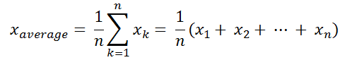
And the RMS value in discrete-time can be calculated using the following equation:

The Arduino uno board microcontroller (ATmega328P) contains a 10-bit ADC module, the positive voltage reference is 2.048V means that a 2.048V is digitally represented by 1023 and 0V is represented by 0 (1 digit for every 2mV).
To get more precise and higher resolution readings, I wrote a simple code to use what’s known as oversampling and decimation technique to add another 2 bits to the 10 bits of the ADC. This gives us a total of useful 12-bit words.
Firstly, I declared an array of 256 elements named r_array , it is used to store reading samples which are used later to calculate average (dc offset) and RMS values.
With oversampling of 2 bits, we’ve to do 16 analog readings for each element of the ‘r_array’ variable. These readings are summed and divided by 4, where 16 = 4² and 4 = 2² and this ² is number of oversampling bits.
Oversampling code is located in a void function named get_smaples() which is used to fill sample array r_array by doing a total of 4096 (16 x 256) successive ADC readings.
Programming hints:
At startup, the Arduino MCU executes an auto calibration code, so before powering the Arduino make sure that there’s no current flows through the ACS758 sensor, otherwise results of DC and AC+DC current calculations may not be accurate, auto calibration has no effect on AC calculations.
I added the auto calibration code to read and record the whole circuit offset voltages which is for example caused by: unsymetrical bipolar supply (±2.5V), ACS758 offset, op amps offset …
The auto calibration code saves the default DC offset values for the 3 gains (10, 1 and 0.5) to a float array of 3 elements, it’s named as: dc_offset[3] .
The Arduino automatically switches between the three gain choices (10, 1 and 0.5) whenever RMS or average voltage applied to analog channel 0 exceeds 500mV, or goes down under 50mV if the gain is 1 and 250mV if the gain is 0.5.
Load current ranges with respect to gain are as follows:
| Gain | Load current range (A) |
| 10 | < 5 |
| 1 | 5 – 50 |
| 0.5 | > 50 |
Functions used in the Arduino code:
void current_type_set(): selection of current type AC, DC or AC+DC is made by pressing the pushbutton connected to digital pin 2. When pressed, the Arduino immediately executes an interrupt routine and then in the loop() function a variable named current_type is incremented which is later used to distinguish between the 3 current types.
void gain_set(uint8_t g): this function is used to change circuit gain according to g.
void get_smaples(): this function fills the sample array mentioned above with 256 12-bit of data.
bool debounce (): used to de-bounce the pushbutton connected to Arduino digital pin 2. Returns true if OK and false if error.
Full Arduino code:
1 2 3 4 5 6 7 8 9 10 11 12 13 14 15 16 17 18 19 20 21 22 23 24 25 26 27 28 29 30 31 32 33 34 35 36 37 38 39 40 41 42 43 44 45 46 47 48 49 50 51 52 53 54 55 56 57 58 59 60 61 62 63 64 65 66 67 68 69 70 71 72 73 74 75 76 77 78 79 80 81 82 83 84 85 86 87 88 89 90 91 92 93 94 95 96 97 98 99 100 101 102 103 104 105 106 107 108 109 110 111 112 113 114 115 116 117 118 119 120 121 122 123 124 125 126 127 128 129 130 131 132 133 134 135 136 137 138 139 140 141 142 143 144 145 146 147 148 149 150 151 152 153 154 155 156 157 158 159 160 161 162 163 164 165 166 167 168 169 170 171 172 173 174 175 176 177 178 179 180 181 182 183 184 185 186 187 188 189 190 191 192 193 194 195 196 197 198 199 200 201 202 203 204 205 206 207 208 209 210 211 | /************************************************************************ * * AC & DC Current measurement using Arduino and Allegro ACS758 current sensor. * Calculated current values are printed on 1602 LCD screen and serial monitor. * This is a free software with NO WARRANTY - Use it at your own risk! * https://simple-circuit.com/ * ************************************************************************/ #include <LiquidCrystal.h> // include Arduino LCD library // LCD module connections (RS, E, D4, D5, D6, D7) LiquidCrystal lcd(5, 6, 7, 8, 9, 10); #define ANALOG_CHANNEL A0 // define analog channel input #define REF_VOLTAGE 2048 // +ive reference voltage for ADC, in millivolts #define ACS758_SENS 10 // ACS758 sensitivity = 10mV/A (for ACS758-200B version) #define CUR_SEL 2 // current type select pushbutton pin // define autoranging control pins #define CH0 3 #define CH1 4 // define current type #define AC 0 // AC current #define DC 1 // DC current #define AC_DC 2 // AC+DC current (AC current with DC offset) // variables byte current_type = AC; // current type according to previous 3 definitions const uint16_t n = 256; // number of samples float _array[n]; // sample array with 'n' elements const float gain_table[3] = {10.0, 1.0, 0.5}; // programmable gains byte gain; // gain variable, may be 0, 1 or 2 float dc_offset[3]; // auto-calibration dc offset array with 3 elements (according to gain) void setup(void) { Serial.begin(9600); pinMode (CUR_SEL, INPUT_PULLUP); pinMode(CH0, OUTPUT); pinMode(CH1, OUTPUT); lcd.begin(16, 2); // set up the LCD's number of columns and rows lcd.setCursor(0, 0); // move cursor to column 0, row 0 [position (0, 0)] lcd.print("ACS758 Current ="); analogReference(EXTERNAL); // set positive reference voltage to external // do auto-calibration to the circuit (no current should flow through the ACS758 sensor) for (byte i = 0; i < 3; i++) { float __offset = 0; gain_set(i); get_smaples(); for (uint16_t j = 0; j < n; j++) __offset += _array[j]; __offset /= n; dc_offset[i] = __offset; } gain = 0; gain_set(gain); attachInterrupt( digitalPinToInterrupt(CUR_SEL), current_type_set, FALLING ); // interrupt enable } volatile bool button = 0; // variable for CUR_SEL button press // set current type: AC, DC or AC+DC void current_type_set() { button = 1; detachInterrupt( digitalPinToInterrupt(CUR_SEL) ); // interrupt disable loop(); } // gain set function void gain_set(uint8_t g) { switch(g) { case 0: digitalWrite(CH0, LOW); digitalWrite(CH1, LOW); break; case 1: digitalWrite(CH0, HIGH); digitalWrite(CH1, LOW); break; case 2: digitalWrite(CH0, HIGH); digitalWrite(CH1, HIGH); } } // analog data acquisition function void get_smaples() { // clear sample array for (uint16_t i = 0; i < n; i++) _array[i] = 0.0; // fill samples array with 12-bit data (add another 2 bits using oversampling technique) for (uint16_t i = 0; i < n; i++) { for (uint16_t j = 0; j < 16; j++) _array[i] += analogRead(ANALOG_CHANNEL); } for (uint16_t i = 0; i < n; i++) { _array[i] /= 4; // reverse readings polarities caused by the inverting amplifier _array[i] = abs( _array[i] - 4096.0 ); } } // button debounce function bool debounce () { byte count = 0; for(byte i = 0; i < 5; i++) { if ( !digitalRead(CUR_SEL) ) count++; delay(10); } if(count > 2) return 1; else return 0; } // main loop function void loop() { if (button) { // if current type button is pressed button = 0; if ( debounce() ) { current_type++; if (current_type > 2) current_type = 0; } attachInterrupt( digitalPinToInterrupt(CUR_SEL), current_type_set, FALLING ); // interrupt enable } // get samples from 'INPUT_CHANNEL' analog pin get_smaples(); float ch_voltage = 0; // Arduino analog channel voltage variable if ( current_type == AC || current_type == AC_DC ) { // AC or AC+DC type float _offset = 0; if ( current_type == AC ) { // AC signal for (uint16_t i = 0; i < n; i++) // caculate signal average value (dc offset) _offset += _array[i]; _offset = _offset / n; } else // AC+DC signal _offset = dc_offset[gain]; // the dc offset is the pre-calibrated one // calculate signal RMS value (digital representation) for (uint16_t i = 0; i < n; i++) { if( abs( _array[i] - _offset ) > 5 ) // apply some filter ch_voltage += sq( _array[i] - _offset ); } ch_voltage = ch_voltage / n; ch_voltage = sqrt(ch_voltage); } else { // DC type for (uint16_t i = 0; i < n; i++) { if( abs(_array[i] - dc_offset[gain] ) > 5 ) // apply some filter ch_voltage += _array[i] - dc_offset[gain] ; // remove the pre-calibrated DC offset } ch_voltage /= n; // average value } // calculate Arduino analog channel input voltage in millivolts ch_voltage = ch_voltage * REF_VOLTAGE / 4096.0; // 4096 is max digital value of 12-bit number (oversampled ADC) if( gain < 2 && abs(ch_voltage) > 500.0 ) { gain++; gain_set(gain); return; } else if ( (abs(ch_voltage) < 50.0 && gain == 1) || (abs(ch_voltage) < 250.0 && gain == 2) ) { gain--; gain_set(gain); return; } // calculate ACS758 sensor output voltage float acs758_voltage = ch_voltage / gain_table[gain] ; // now we can calculate current passing through the ACS758 sensor (in amps) float acs758_current = acs758_voltage / ACS758_SENS ; lcd.setCursor(0, 1); Serial.print( "ACS758 Current = " ); if ( acs758_current < -0.01) { lcd.print('-'); Serial.print('-'); } acs758_current = abs(acs758_current); lcd.print( acs758_current ); Serial.print( acs758_current ); if ( current_type == AC ) { lcd.print( "A AC "); Serial.println( "A AC"); } else if ( current_type == DC ) { lcd.print( "A DC "); Serial.println( "A DC"); } else { lcd.print( "A AC+DC "); Serial.println( "A AC+DC"); } Serial.println(); } // end of code. |
Measure AC & DC Current with Arduino and ACS758 Sensor Video:
The following video shows my DIY circuit for this project, I used a clamp meter from UNI-T company (UT219DS) in order to test the accuracy of my circuit.
Note that some wires connecting the Arduino uno and the DIY PCB are soldered on the back of the two boards, this removes small voltages & noise caused by poor connections between jumper wires and Arduino board female header pins.
Related Projects:
Electric Current Measurement Using Arduino and ACS758 Sensor
AC & DC Current Measurement with Arduino and LTSR 25-NP Sensor
Discover more from Simple Circuit
Subscribe to get the latest posts sent to your email.


Hello. Great project! I’m learning electronics and have a few questions about the design:
1) Why is U2.B in inverting mode? Utilizing the non-inverting mode might enable the use of inexpensive MOSFETs to control gain, instead of the relatively expensive switch IC. A gain of 0.5 might not be necessary if the ADC reference were 4V or 5V.
2) Considered utilizing Arduino’s +5V supply to power the current sensor IC (despite its lack of precision, it still offers stability). A resistor divider could be employed to obtain half of the supply voltage, and then a unity gain OpAmp could establish a reference point for subsequent amplification of signal from current sensor. Furthermore, maintaining Arduino’s default reference voltage equal to the power supply could be beneficial in that case. This setup could result in imprecise but stable supply voltages for both the current sensor IC and ADC, ensuring consistency. This is crucial as the current sensor’s output is dependent on the supply voltage.
3) Additionally, I came across an interesting concept – after the sensor, the AC signal could be rectified using an ideal rectifier (incorporating an OpAmp). However, the polarity could be preserved as separate digital signal. Subsequently, both signals could be fed to the ADC and a digital pin. This configuration would enable the utilization of 2×ADC bit resolution.