There are two types of BLDC motors: sensored and sensorless. Sensored BLDC motor uses hall effect sensors to detect rotor position where as the sensorless BLDC motor uses another technique which is BEMF (back electromotive force). This topic shows how to drive a sensored BLDC motor using an Arduino UNO board. The BLDC motor used in this project is just a PC CD-ROM motor (spindle motor).
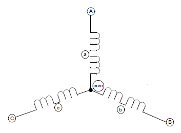
The BLDC motor (sensored or sensorless) is a 3 phase DC motor which means it has 3 winding on the stator core. Two coils are energized at a time to create a rotating electric field. This method is fairly easy to implement, but to prevent the permanent magnet rotor from getting locked with the stator, the excitation on the stator must be sequenced in a specific manner while knowing the exact position of the rotor magnets.
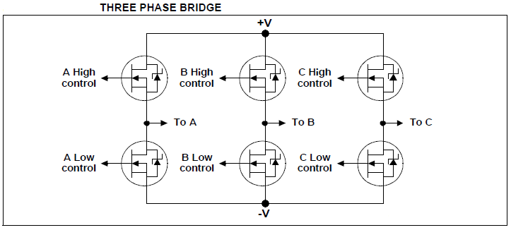
To drive this motor we need a 3-phase bridge, the basic elements of it are the 6 MOSFETs. General circuit schematic diagram of the 3-phase bridge is shown below:
The sensored BLDC motor has 3 hall effect sensors (A, B and C) to sense rotor position, these sensors are placed as shown in the following picture. The motor which I used in this project has pinout as shown below (other motors may have a different pinout).
In this motor each hall effect sensor has 4 pins: VCC (H+), GND (H-) and two outputs (some sensors come with 3 pins: VCC, GND and output).
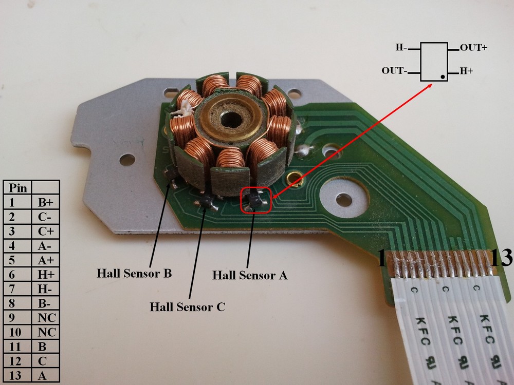
Since I have 4-pin hall effect sensors, I added an analog comparator (I used LM339N quad comparator IC) to each one so each sensor outputs (2 outputs: + and -) are connected to the inputs (2 inputs: non-inverting and inverting) of the comparator as shown in the circuit schematic below, finally I got 3 outputs from the 3 hall effect sensors.
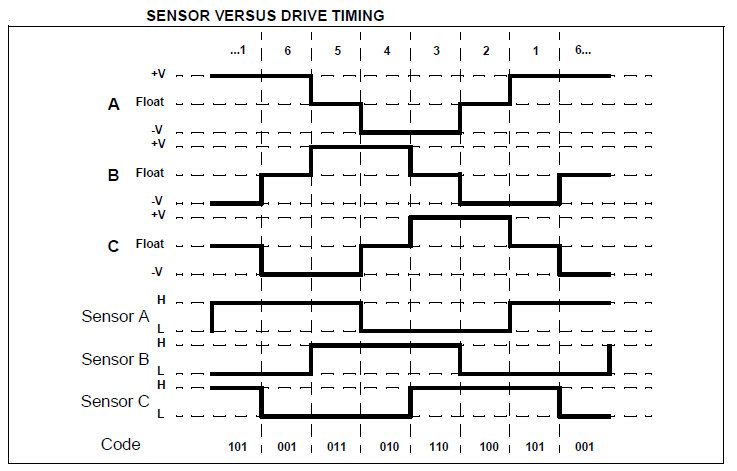
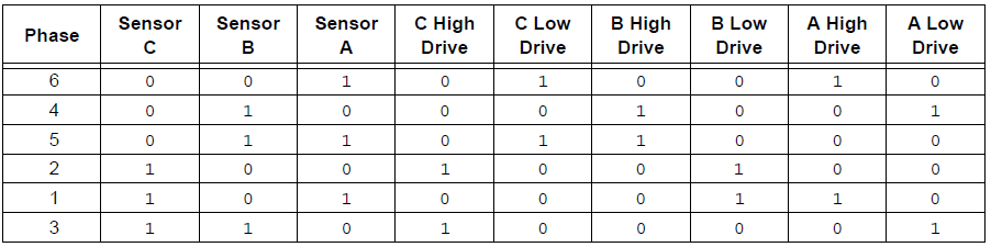
Each sensor outputs a digital high for 180 electrical degrees and outputs a digital low for the other 180 electrical degrees. The following figure shows the relationship between the sensors outputs and the required motor drive voltages for phases A, B and C.
According to the hall effect sensors, the 3-phase bridge is controlled as shown in the following table:
Components Required:
- Arduino board —> ATmega328P datasheet
- Sensored brushless DC motor
- 6 x 06N03LA N-type mosfet (or equivalent) —> datasheet
- 3 x IR2104S gate driver IC – datasheet
- LM339N (or LM339) quad comparator IC —> datasheet
- 10k ohm (or less) potentiometer
- 3 x 10k ohm resistor
- 7 x 100 ohm resistor
- 3 x IN4148 diode
- 3 x 10uF capacitor
- 3 x 2.2uF capacitor
- 12V source
- Breadboard
- Jumper wires
Sensored brushless DC motor control with Arduino circuit:
The overall circuit diagram is shown below.
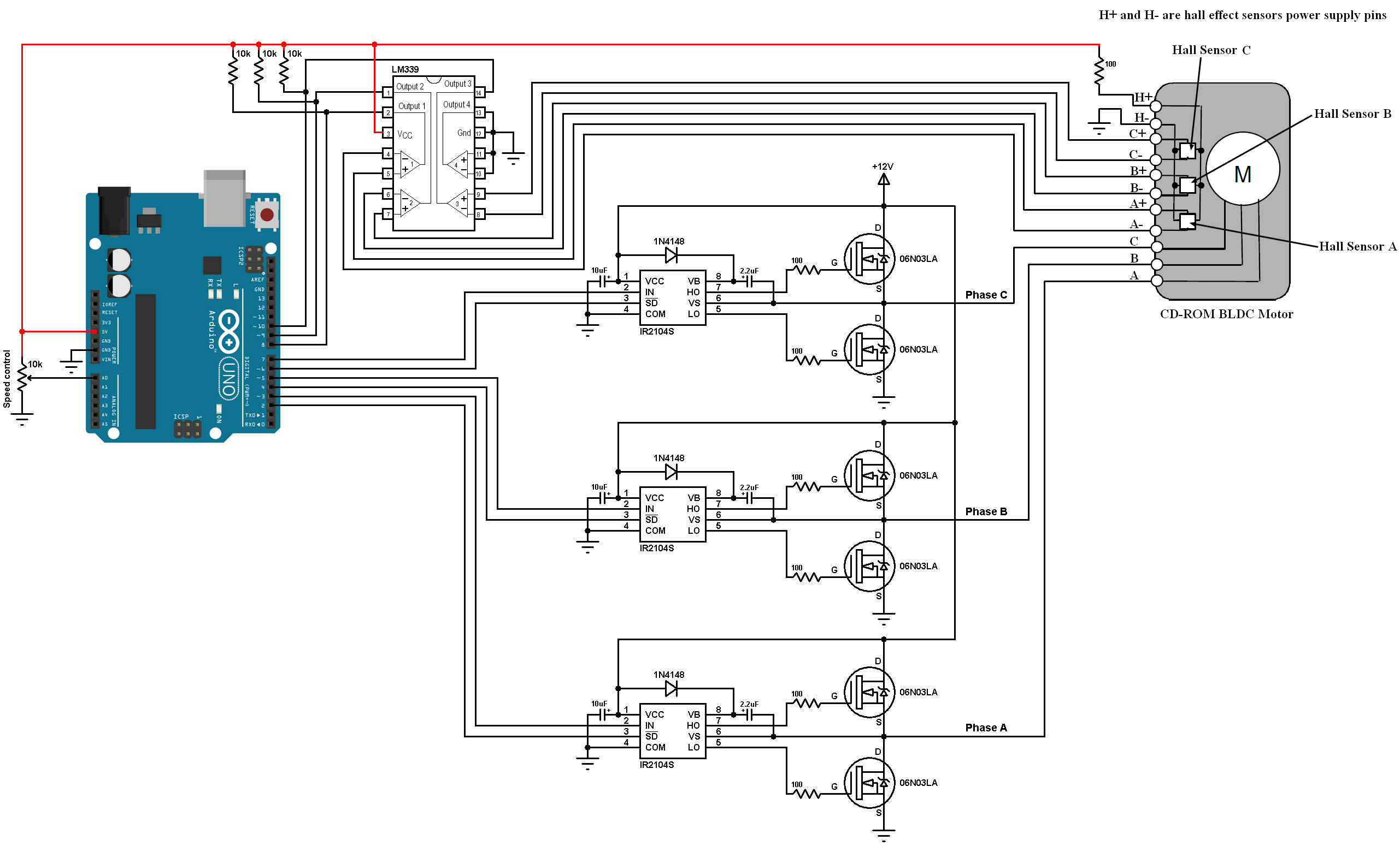
(All grounded terminals are connected together).
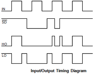
In the circuit there are three IR2104S gate driver IC, each one is used to drive one high side mosfet and one low side mosfet, the switching between the high side and the low side is done according to the control lines which are: IN and SD. The figure below shows input and output timing diagram:
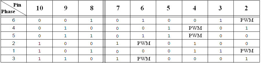
The 10k potentiometer is used to control the brushless DC motor speed, it is controlled using PWM technique (pwming high sides only). Any time there is one active high side mosfet and one active low side mosfet, that means always there is one active PWM pin (Arduino pin 2, 4 or 6).
The table below summarizes the active Arduino pins according to the hall effect senors states (pins: 8, 9, and 10):
Sensored brushless DC motor control with Arduino code:
In this project I implemented a simple software PWM code because I had needed an active PWM signal on pin 2, 4 or 6 (only one is active at a time), for that I used Timer2 module and I configured it with a prescaler of 1/8 which means the PWM signal frequency is about 7.8KHz ( equal to: 16MHz/(8 * 256) ) and 8-bit resolution.
The ADC module is configured to read from channel 0 only.
Arduino interrupt on change is activated for pins 8, 9 and 10 (hall effect sensors inputs) for better commutation.
PORTB are Arduino uno pins: 8 … 13.
PORTD are Arduino uno pins: 0 … 7.
1 2 3 4 5 6 7 8 9 10 11 12 13 14 15 16 17 18 19 20 21 22 23 24 25 26 27 28 29 30 31 32 33 34 35 36 37 38 39 40 41 42 43 44 45 46 47 48 49 50 51 52 53 54 55 56 57 58 59 60 61 62 63 64 65 66 67 68 | // Arduino sensored BLDC (brushless DC) motor control code // https://simple-circuit.com/ byte motor_speed, bldc_step, pwm_pin = 2; void setup() { DDRD |= 0xFC; // Configure pins 2, 3, 4, 5, 6 and 7 as outputs PCICR = 1; // Enable pin change interrupt for pins 8 to 13 PCMSK0 = 7; // Enable pin change interrupt for pins 8, 9 and 10 // Timer2 configuration TCCR2A = 0; TCCR2B = 2; // Timer2 prescaler = 1/8 (Timer2 clock = 2MHz) TCNT2 = 0; // Timer2 preload value = 0 // ADC module configuration ADMUX = 0x60; // Configure ADC module and select channel 0 ADCSRA = 0x84; // Enable ADC module with 16 division factor (ADC clock = 1MHz) // BLDC motor first move bldc_step = PINB & 7; // Read hall effect sensors status (PINB: read from PORTB which is arduino pins 8..13) bldc_move(); // Move the BLDC motor (first move) } ISR (PCINT0_vect){ bldc_step = PINB & 7; // Read and save hall effect sensors status (PINB: read from PORTB which is arduino pins 8..13) bldc_move(); // Move the BLDC motor } void bldc_move(){ // BLDC motor move function according to hall effect sensors status switch(bldc_step){ case 1: PORTD = 0x48; pwm_pin = 2; break; case 2: PORTD = 0x24; pwm_pin = 4; break; case 3: PORTD = 0x60; pwm_pin = 4; break; case 4: PORTD = 0x90; pwm_pin = 6; break; case 5: PORTD = 0x18; pwm_pin = 2; break; case 6: PORTD = 0x84; pwm_pin = 6; break; default: PORTD = 0; break; } } void loop() { ADCSRA |= 1 << ADSC; // Start conversion while(ADCSRA & 0x40); // Wait for conversion complete motor_speed = ADCH; // Read ADC data (8 bits) // Software PWM if(motor_speed < 250){ while(TCNT2 < motor_speed) ; digitalWrite(pwm_pin, LOW); } if(motor_speed > 0){ while(TCNT2 >= motor_speed) ; digitalWrite(pwm_pin, HIGH); } } |
Sensored brushless DC motor control with Arduino video:
The video below shows a hardware circuit of the project:
Related Project:
CD-ROM Sensored BLDC motor control with Arduino
Discover more from Simple Circuit
Subscribe to get the latest posts sent to your email.


Thank you for this knowledge, you are the best
Hola
espero que se encuentre muy bien, queria saber si tubiste exito al istalar los sensor hall de 3 pines ( 41f, hall) yo pensaria usar estos., que cambios hiciste en la conexion del LM 339 y en el codigo de arduino
desde ya, muchas gracias por tus respuestas.
ATT
HAVG
+573205883410
Hi man,
there are a question about over speed of bldc motor with hall sensor.
is Hall sensor prohibited over speed ?
I look at internet , and I saw some text about hall sensor prohibited over speed for example over 10000 rpm , is it true?
Goodbye MAN
Hello
Thanks for the circuit
is it possible to use a PWM input instead of the button?
if the signal is less than 20 should the engine stop?
Do I need a second PWM input for the brake?
It would be great if you could help me with that
Thanks
Roland
We are facing problem in running our 3 phase sensorless brushless dc motor can you please guide us?
Our motor has 8 pins
3 of motor windings
2 of vcc ground of halls
3 hall pins
Can you please help us in making it’s driver board we want to control this motor with arduino uni board
Also we need some guidance in it’s coding
projen ne durumda bende aynı projeyi yapıyorum bitirme tezi olarak
It would of great help to me if you could tell how to change the direction of motor rotation. I am working on a project which requires the motor to rotate both in clockwise (CW) and counter clockwise (CCW) direction.
Thank you so much for this amazing post.
Hi, Do you think it is possible to use the same circuit for 220 volts is I change the mosfets for higher specifications – are there any you would recommend. Thanks Anthony
sir which software did u use?
I am building this circuit with the following modifications. I am using 9v to power the circuit, but using higher voltages where power is gated by the MOSFETs for higher power motors. The two input voltages will share a common ground. Do you foresee any difficulties with this approach?
Will it works on 36 or 48V??
Thank you so much for your excellent tutorial. Do you know how can we reverse the direction of the motor ? I appreciate your help.
pin no 3,5 and 7 whe
re these pins are what was actually dose in the program??
Thank you for this beautiful and efficient jewel of a code.
it was very inspiring for me.
Sebastian
Hi. Thanks for sharing this project. It was a good inspiration.
I noticed that you have the SOIC IR2102 mounted into some sort of socket … What are those sockets and where can I buy them ?
They are IR2104S, soldered in SOP to DIP converter PCBs. The sockets are just pin headers, you can get them from online shopping websites (Aliexpress, ebay …).
How to change the program from 180degree bldc timing to 120 degree. because mine is 120 degree
https://community.parker.com/technologies/electromechanical-group/w/electromechanical-knowledge-base/174/hall-sensors-60-vs-120degrees
@ william Its 120 phase difference between hall sensors. In this post Note that Hall states retain for 180 deg, But the difference between each hall is 120
Thank you for your contributions, this very illustrative and schematic project, you learn from your projects, they serve as guides and inspirations.
a question I would like to know how to adapt this project to a hall sensor of three terminals, what change should be made to use the sensor hall three terminals, thank you for your ingenuity and creativity
Can we control the speed using push buttons? please help me with the changes in code to do so.
How you change direction ?
Hi,
I am trying to make a 5 phase BLDC motor controller and your 3 phase example is by far the best I’ve seen! Is it possible for me to implement code like this to make a 5 phase controller?
I also want to add that I am quite the noob with arduino and although I understand the read/write parts of the code, I do not understand how to enable and assign the interrupt pins using this port manipulation method and the software PWM section.
I looked around and could not find a good enough tutorial using data port manipulation.
Will you please explain this to me?
Thanks
Thanks very much
Hi, I suppose I understood that you are using software based PWM.
Thanks
This article is great. I like it very much
But I have a liite question. You say Arduino pins 2, 4 and 6 as PWM capable but I find only pins 3,5,6,9,10,11 are PWM cable.
This is clear from the picture of the UNO in your schematic.
Could you kindly explain me this discrepancy.
Thanks
In this project a software PWM is used which can be used with any pin, but it’s recommended to use hardware PWM as what was done in this project:
CD-ROM Sensored BLDC motor control with Arduino
Actually I am using bldc controlling in order to obtain regenerative braking ; would this program be enough to get regenerative braking voltage