This is another post that shows how to measure AC and DC currents using Arduino. The current sensor used in this project is LTSR 25-NP hall-effect current sensor which can be used to measure AC and DC currents.
A 1602 LCD connected to the Arduino board is used to display current values, the Arduino also sends the same values to the Laptop which can be viewed using serial monitor.
A pushbutton connected to the Arduino board to choose between AC and DC currents.
Hints:
No warranty is provided with this project, so do it at your own risk!
A part of project circuit may be subjected to high voltage which is very harmful to human body, so be-careful!
Abbreviations:
AC: Alternating Current
DC: Direct Current
TRMS: True Root Mean Square
ADC: Analog-to-Digital Converter
PCB: Printed Circuit Board
DIY: Do It Yourself
Op amp: operational amplifier
About LTSR 25-NP current sensor:
The LTSR 25-NP is a small current sensor designed for direct PCB mounting. This sensor belongs to the LTSR series of hall-effect based current sensors from LEM. This sensor generates a voltage that is proportional to the current passing through it where the generated voltage is galvanically isolated from the passing current. This means at all times, high power circuit is isolated from low power circuit.
The LTSR series consists of 3 types according to nominal primary RMS current IPN:
LTSR 25-NP —> IPN = 25A
LTSR 15-NP —> IPN = 15A
LTSR 6-NP —> IPN = 6A
This type of sensors can be used to measure AC and DC currents with very good accuracy, they are also easy to use which makes them a good choice for DIY and hobbyists projects.
The LTSR sensor is supplied with unipolar supply voltage of 5 Volts. At 0 A load current, the output of this sensor is 2.5V which is the same as an internal band gap reference voltage. The sensor provides this reference voltage at Ref pin (ref in mode). The user also is able to apply an external voltage reference (ref out mode) with voltage between 1.9 and 2.7V .
At nominal primary current, the LTSR sensor output voltage is 3.125V, it is just the offset voltage (2.5V) plus nominal primary current multiplied by device sensitivity.
The sensitivity of the LTSR 25-NP sensor is 25mV/A, whereas the LTSR 15-NP has a sensitivity of 41.6mV/A and the LTSR 6-NP is 104.16mV/A .
Current measurement with Arduino and LTSR 25-NP sensor circuit:
Project circuit diagram is shown below (click on the image for better view).
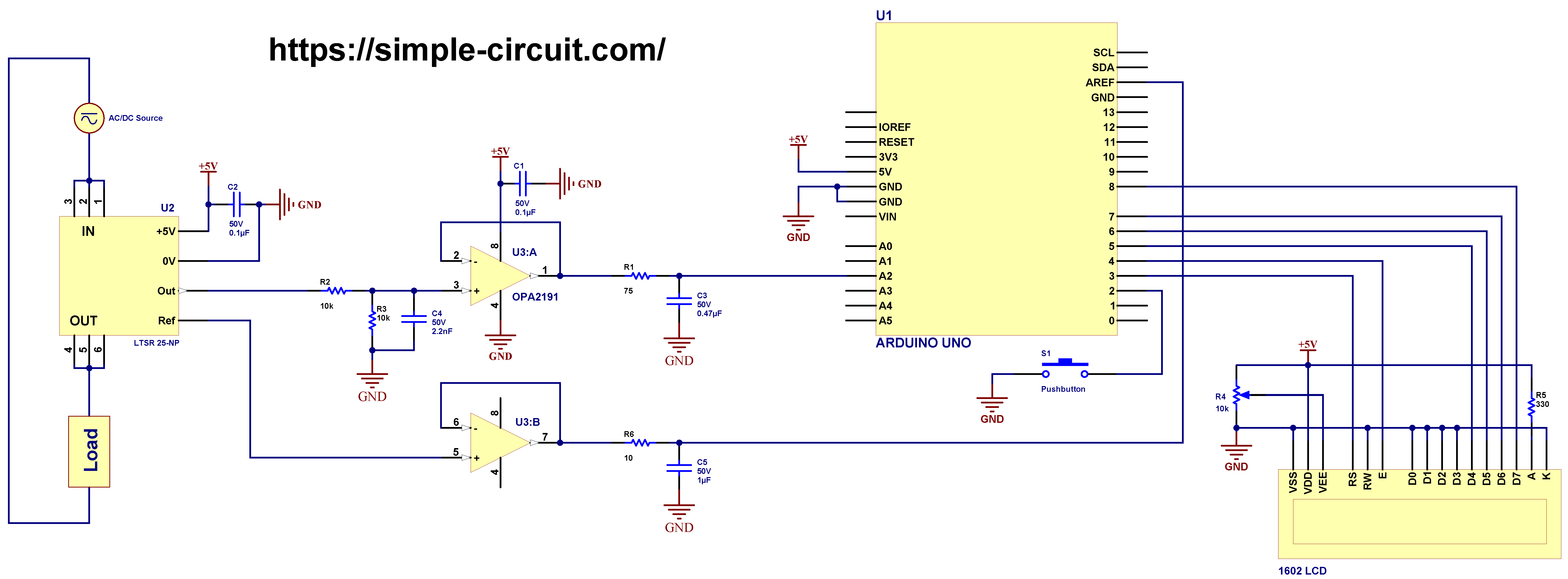
Note that in the circuit there is 1 ground only which is the same as Arduino board ground (GND).
The Arduino uno board is represented by U1 and the LTSR 25-NP by U2.
As shown in circuit schematic, the LTSR 25-NP current sensor is connected between the AC/DC source and the load. Instead of the LTSR 25-NP the other 2 models of the same LTSR series can also be used (LTSR 15-NP and LTSR 6-NP), the only thing has to be changed is device sensitivity in Arduino code.
The voltage source may be AC or DC according to the connected load.
Hardware required:
This is a summary of circuit required parts (circuit schematic diagram may contain some component parameters not mentioned below).
- Arduino Uno or equivalent board such as Arduino Nano (U1)
- LTSR series current sensor (LTSR 25-NP, LTSR 15-NP, LTSR 6-NP) (U2) —> LTSR 25-NP datasheet
- OPA2191 op amp (U3) —> details
- 1602 LCD screen
- 1 µF capacitor (C5)
- 0.47 µF capacitor (C3)
- 2 x 0.1 µF capacitor (C1, C2)
- 2.2 nF capacitor (C4)
- 2 x 10k Ohm resistor (R2, R3)
- 330 Ohm resistor (R5)
- 75 Ohm resistor (R1)
- 10 Ohm resistor (R6)
- 10k variable resistor (R2)
- Pushbutton (S1)
- Breadboard
- Jumper wires
Circuit description:
The LTSR 25-NP current sensor is noted in the circuit schematic above as U2. It is supplied with voltage of 5V from the Arduino board.
Basically, the LTSR 25-NP has total of 10 pins, the 6 numbered pins are for high voltage (1 ~ 6) and the rest 4 are low voltage pins.
The low voltage pins are: +5V, 0V, Out and Ref. The +5V and 0V pins are sensor power supply pins and they are respectively connected to Arduino board 5V and GND.
LTSR 25-NP Out is sensor output voltage pin, the voltage at this pin is proportional to the current flowing through the sensor.
The output signal from the current sensor is filtered and attenuated using resistors R2 & R3 and capacitor C4. The filtrated signal is then goes to an op amp voltage follower circuit in order to properly buffer that signal, the op amp used in this project is OPA2191.
After the buffer circuit, the signal is filtered again using resistor R1 and capacitor C3 and then goes directly to Arduino analog channel 2.
The OPA2191 from Texas Instruments contains 2 independent op amps in one package. The first op amp (A) is used to buffer the LTSR 25-NP output voltage as described above.
The 2nd op amp (B) is also used as a voltage follower for the LTSR 25-NP sensor internal band gap reference (2.5V) from sensor’s Ref pin. The output of op amp B is connected to a RC circuit and then to Arduino AREF pin, it is used as positive voltage reference for the Arduino ADC module.
The 1602 LCD screen (2 rows and 16 columns) is used to display the value of the current that flows through the LTSR 25-NP sensor (load current), it is connected to the Arduino board as follows:
RS —> Arduino digital pin 3
E —> Arduino digital pin 4
D4 —> Arduino digital pin 5
D5 —> Arduino digital pin 6
D6 —> Arduino digital pin 7
D7 —> Arduino digital pin 8
VSS, RW, D0, D1, D2, D3 and K are connected to GND,
VEE to the 10k Ohms variable resistor (or potentiometer) output,
VDD to Arduino 5V and A to Arduino 5V through 330 ohm resistor.
VEE pin is used to control the contrast of the LCD. A (anode) and K (cathode) are the back light LED pins.
The pushbutton (connected to Arduino digital pin 2) is used to choose between 3 current types: AC, DC or AC+DC.
With the Arduino code below and when AC type is selected, the Arduino calculates TRMS value of the AC current flows through the LTSR 25-NP sensor, any DC current will not be included in the results.
Alternatively, when DC type is selected, the Arduino calculates average (mean) value of the current applied to the LTSR 25-NP sensor.
However, when AC+DC type is selected, the Arduino calculates TRMS value of the current that passes through the LTSR 25-NP sensor where the DC component (offset) is included in calculations.
Current measurement with Arduino and LTSR 25-NP sensor code:
Project code is the one below, it was tested with Arduino UNO board.
This Arduino code calculates RMS values for AC and AC+DC currents, and average (mean) values for DC current. The user can switch between the 3 current calculation modes using the pushbutton connected to Arduino digital pin 2, the default current type is AC (at startup).
Simply the average (mean or DC offset) value in discrete-time is the sum of all sample values divided by number of samples:

And the RMS value in discrete-time can be calculated using the following equation:

The Arduino uno board microcontroller (ATmega328P) contains a 10-bit ADC module, the positive voltage reference is 2.5V means that a 2.5V is digitally represented by 1023 and 0V is represented by 0.
To get more precise and higher resolution readings, I wrote a simple code to use what’s known as oversampling and decimation technique to add another 2 bits to the 10 bits of the ADC. This gives us a total of useful 12-bit words.
Firstly, I declared an array of 256 elements named r_array , it is used to store reading samples which are used later to calculate average (dc offset) and RMS values.
With oversampling of 2 bits, we’ve to do 16 analog readings for each element of the ‘r_array’ variable. These readings are summed and divided by 4, where 16 = 4² and 4 = 2² and this ² is number of oversampling bits.
Oversampling code is located in a void function named get_smaples() which is used to fill sample array r_array by doing a total of 4096 (16 x 256) successive ADC readings.
Programming hints:
At startup, the Arduino MCU executes an auto calibration code, so before powering the Arduino make sure that there’s no current flows through the LTSR 25-NP sensor, otherwise results of DC and AC+DC current calculations may not be accurate, auto calibration has no effect on AC calculations.
I added the auto calibration code to read and save circuit default offset voltage. The auto-calibrated DC offset value is saved to a float variable named: dc_offset.
Functions used in the Arduino code:
void current_type_set(): selection of current type AC, DC or AC+DC is made by pressing the pushbutton connected to digital pin 2. When pressed, the Arduino immediately executes an interrupt routine and then in the loop() function a variable named current_type is incremented, it is later used to distinguish between the 3 current types.
void gain_set(uint8_t g): this function is used to change circuit gain according to g.
void get_smaples(): this function fills the sample array mentioned above with 256 12-bit of data.
bool debounce (): used to debounce the pushbutton connected to Arduino digital pin 2. Returns true if OK and false if error.
Full Arduino code:
1 2 3 4 5 6 7 8 9 10 11 12 13 14 15 16 17 18 19 20 21 22 23 24 25 26 27 28 29 30 31 32 33 34 35 36 37 38 39 40 41 42 43 44 45 46 47 48 49 50 51 52 53 54 55 56 57 58 59 60 61 62 63 64 65 66 67 68 69 70 71 72 73 74 75 76 77 78 79 80 81 82 83 84 85 86 87 88 89 90 91 92 93 94 95 96 97 98 99 100 101 102 103 104 105 106 107 108 109 110 111 112 113 114 115 116 117 118 119 120 121 122 123 124 125 126 127 128 129 130 131 132 133 134 135 136 137 138 139 140 141 142 143 144 145 146 147 148 149 150 151 152 153 154 155 156 157 158 159 160 161 162 163 164 165 166 167 168 169 170 171 172 173 174 175 176 | /************************************************************************ * * AC & DC Current measurement using Arduino and LTSR 25-NP current sensor. * Calculated current values are printed on 1602 LCD screen and serial monitor. * This is a free software with NO WARRANTY - Use it at your own risk! * http://simple-circuit.com/ * ************************************************************************/ #include <LiquidCrystal.h> // include Arduino LCD library // LCD module connections (RS, E, D4, D5, D6, D7) LiquidCrystal lcd(3, 4, 5, 6, 7, 8); #define REF_VOLTAGE 2500.0 // external reference voltage, in millivolts #define LTSR_SENS 25.0 // LTSR 25-NP sensitivity = 25mV/A (41.6 for LTSR 15-NP and 104.16 for LTSR 6-NP) #define CUR_SEL 2 // current type select pushbutton pin // define current type #define AC 0 // AC current #define DC 1 // DC current #define AC_DC 2 // AC+DC current (AC current with DC offset) // variables byte current_type = AC; // current type according to previous 3 definitions const uint16_t n = 256; // number of samples float _array[n]; // sample array with 'n' elements float dc_offset; // auto-calibration dc offset void setup(void) { Serial.begin(9600); pinMode (CUR_SEL, INPUT_PULLUP); lcd.begin(16, 2); // set up the LCD's number of columns and rows lcd.setCursor(0, 0); // move cursor to column 0, row 0 [position (0, 0)] lcd.print("Current ="); // ADC configuration // ADC auto triggering is enabled, ADC clock division factor set to 128 (ADC clock = 125kHz) ADCSRA |= (1 << ADATE) | (1 << ADPS2) | (1 << ADPS1) | (1 << ADPS0); ADMUX |= (1 << MUX1) ; // select analog channel 2 (A2) as input to ADC, +ive is AREF by default // do auto-calibration to the circuit (no current should flow through the ACS758 sensor) dc_offset = 0; get_smaples(); for (uint16_t j = 0; j < n; j++) dc_offset += _array[j]; dc_offset /= n; if ( (dc_offset > 2070.0) || (dc_offset < 2025.0) ) // 2070 corresponds to about 2525mV and 2025 to about 2475mV dc_offset = 2048.0; attachInterrupt( digitalPinToInterrupt(CUR_SEL), current_type_set, FALLING ); // interrupt enable } volatile bool button = 0; // variable for CUR_SEL button press // set current type: AC, DC or AC+DC void current_type_set() { button = 1; detachInterrupt( digitalPinToInterrupt(CUR_SEL) ); // interrupt disable loop(); } // button debounce function bool debounce () { byte count = 0; for(byte i = 0; i < 5; i++) { if ( !digitalRead(CUR_SEL) ) count++; delay(10); } if(count > 2) return 1; else return 0; } // analog data acquisition function void get_smaples() { // clear sample array for (uint16_t i = 0; i < n; i++) _array[i] = 0.0; ADCSRA |= (1 << ADEN) | (1 << ADSC) ; // enable ADC module and start converion (free running mode) // ignore the first reading while ( (ADCSRA & (1 << ADIF)) == 0 ); // wait for ADIF to be set (conversion complete) ADCSRA = ADCSRA; // reset ADIF flag bit // fill samples array with 12-bit data (add another 2 bits using oversampling technique) for (uint16_t i = 0; i < n; i++) { for (uint16_t j = 0; j < 16; j++) { while ( (ADCSRA & (1 << ADIF)) == 0 ); // wait for ADIF to be set (conversion complete) ADCSRA |= (1 << ADIF); // reset ADIF bit by writing 1 to it _array[i] += ADCW; } } ADCSRA &= ~((1 << ADEN) | (1 << ADSC)) ; // stop conversion and disable ADC module, reset ADIF bit also for (uint16_t i = 0; i < n; i++) _array[i] /= 4.0; } // main loop function void loop() { if (button) { // if current type button is pressed button = 0; if ( debounce() ) { current_type++; if (current_type > 2) current_type = 0; } attachInterrupt( digitalPinToInterrupt(CUR_SEL), current_type_set, FALLING ); // interrupt enable return; } // read Arduino analog channel voltage float ch_voltage = 0; // Arduino analog channel input voltage variable get_smaples(); if ( current_type == AC || current_type == AC_DC ) { // AC or AC+DC type float _offset = 0; if ( current_type == AC ) { // AC signal for (uint16_t i = 0; i < n; i++) // caculate signal average value (dc offset) _offset += _array[i]; _offset = _offset / n; } else // AC+DC signal _offset = dc_offset; // the dc offset is the pre-calibrated one // calculate signal RMS value (digital representation) for (uint16_t i = 0; i < n; i++) { if( abs( _array[i] - _offset ) > 2 ) // apply some filter ch_voltage += sq( _array[i] - _offset ); } ch_voltage = ch_voltage / n; ch_voltage = sqrt(ch_voltage); } else { // DC type for (uint16_t i = 0; i < n; i++) { if( abs( _array[i] - dc_offset ) > 2 ) // apply some filter ch_voltage += _array[i] - dc_offset ; // remove the pre-calibrated DC offset } ch_voltage /= n; // average value } ch_voltage = ch_voltage * REF_VOLTAGE / 4096.0 ; // 4096 is max digital value of 12-bit number (oversampled ADC) // calculate actual LTSR 25-NP sensor output voltage float ltsr_voltage = ch_voltage * 2.0 ; // 2.0 is circuit voltage divider // now we can calculate current passing through the LTSR 25-NP sensor (in amps) float ltsr_current = ltsr_voltage / LTSR_SENS ; lcd.setCursor(0, 1); Serial.print( "Current = " ); if ( ltsr_current < -0.01) { lcd.print('-'); Serial.print('-'); } ltsr_current = abs(ltsr_current); lcd.print( ltsr_current ); Serial.print( ltsr_current ); if ( current_type == AC ) { lcd.print( "A AC "); Serial.println( "A AC"); } else if ( current_type == DC ) { lcd.print( "A DC "); Serial.println( "A DC"); } else { lcd.print( "A AC+DC "); Serial.println( "A AC+DC"); } Serial.println(); } // end of code. |
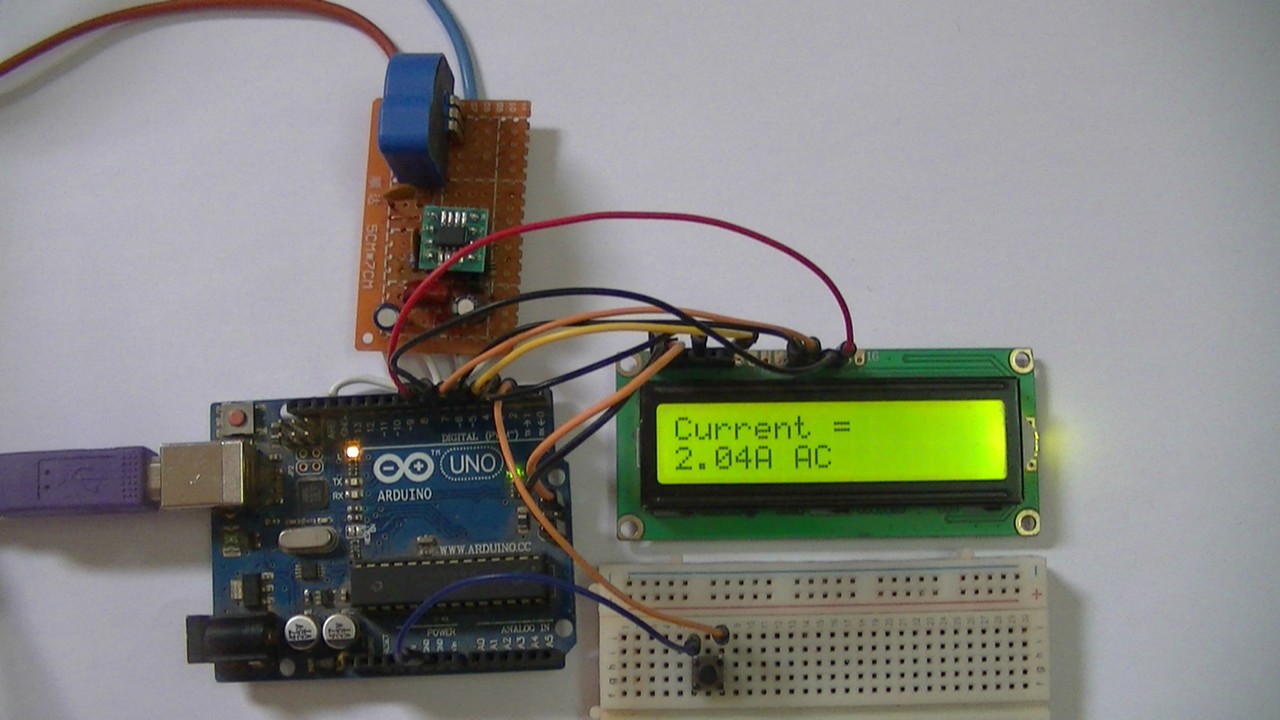
The following small video shows my DIY circuit for this project, to test the accuracy of my circuit I connected a multimeter in series between the LTSR 25-NP sensor and the load.
Note that wires connecting the Arduino uno and the DIY PCB are soldered on the back of the two boards, this removes small voltages & noise caused by poor connections between jumper wires and Arduino board female header pins.
Related Projects:
AC Current Measurement using Arduino and Current Transformer
Measure AC & DC Currents with Arduino and ACS758 Sensor
Interfacing Arduino with Current Transformer – AC Current Measurement
AC Current Measurement using Arduino and Current Transformer
Discover more from Simple Circuit
Subscribe to get the latest posts sent to your email.


it;s a excllent article !! the progress is very details