This is an other simple PIC project that shows how to interface PIC18F46K22 microcontroller with BMP280 barometric pressure and temperature sensor from Bosch Sensortec.
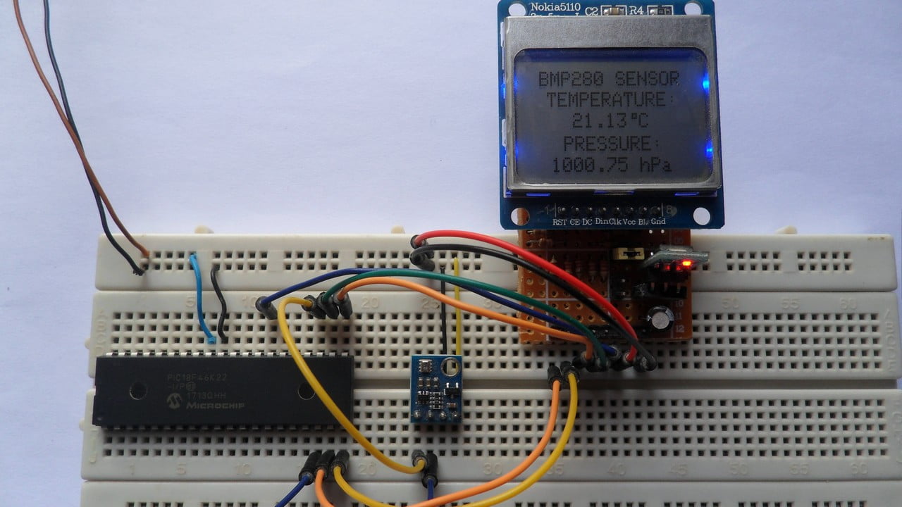
The PIC18F46K22 MCU reads temperature & pressure values from the BMP280 sensor and print them (respectively in °C and hPa) on Nokia 5110 LCD (84×48 pixel resolution).
The compiler used in this project is MikroElektronika mikroC PRO for PIC.
The BMP280 sensor is used in I2C mode.
To see how to interface PIC18F46K22 MCU with Nokia 5110 LCD using mikroC compiler, visit this post:
Interfacing PIC MCU with Nokia 5110 LCD | mikroC Projects
and to see how to interface PIC microcontroller with BMP280 sensor using mikroC PRO for PIC compiler, take a look at this project:
PIC MCU with BMP280 temperature and pressure sensor | mikroC Projects
Hardware Required:
- PIC18F46K22 microcontroller —-> datasheet
- Nokia 5110 LCD screen
- BMP280 sensor module (with built-in 3.3V regulator and level shifter) —-> BMP280 datasheet
- AMS1117 3V3 voltage regulator
- 10 uF capacitor
- 100 nF ceramic capacitor
- 5 x 3.3k ohm resistor
- 5 x 2.2k ohm resistor
- Breadboard
- Jumper wires
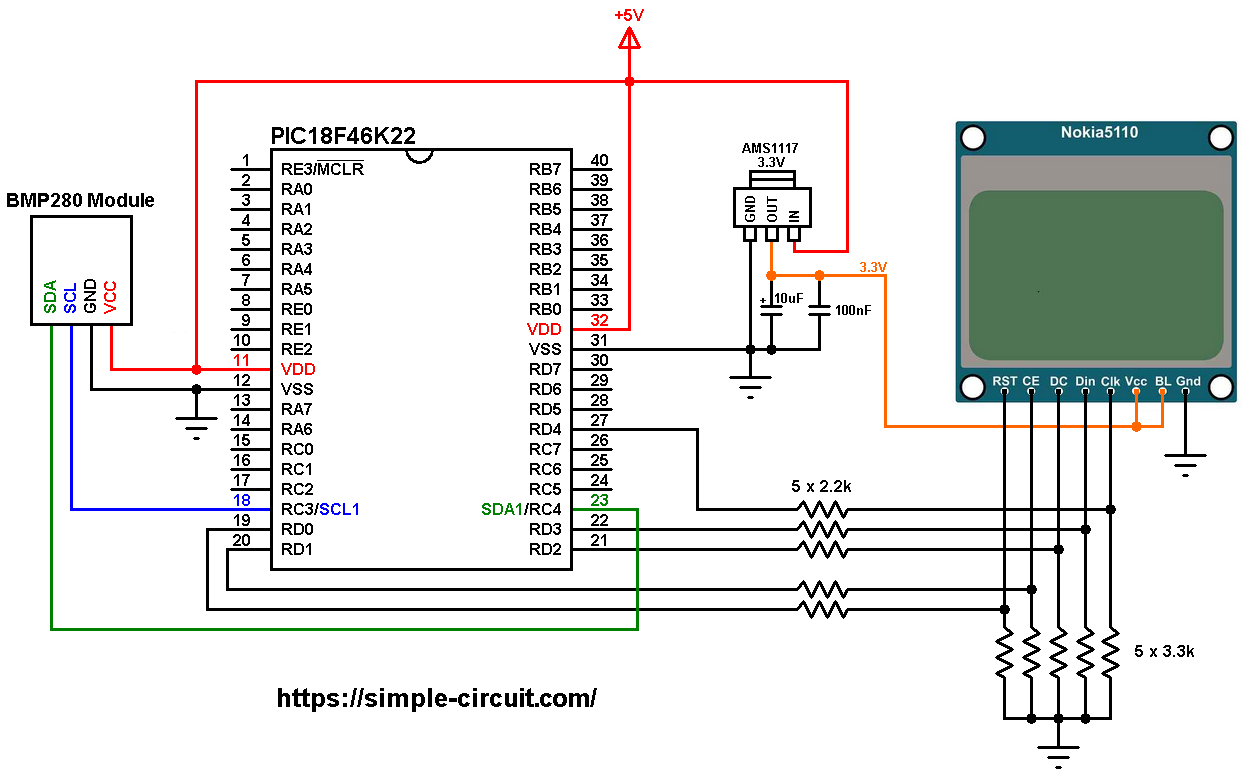
PIC18F46K22 with BMP280 Sensor and Nokia 5110 LCD circuit:
The image below shows project circuit diagram.
Hint:
The BMP280 chip works with maximum voltage of 3.6V (supply voltage range is from 1.71 to 3.6V) which means we’ve to use a 3V3 voltage regulator to supply it from a 5V source.
Also, if we’re working with a 5V system (development board, microcontroller …) like the PIC18F46K22 microcontroller, we’ve to use a voltage level shifter (level converter) which converts the 3.3V (comes from the BMP280 chip) into 5V (goes to the PIC18F46K22) and vice versa. This level shifter is for the I2C bus lines (clock and data).
The BMP280 module shown in project circuit diagram has a built-in 3.3V regulator and level shifter.
All the grounded terminals are connected together.
The PIC18F46K22 microcontroller has 2 hardware I2C modules (MSSP1 and MSSP2 modules).
In this project I2C1 module is used with SDA1 on pin RC4 (#23) and SCL1 on pin RC3 (#18). SDA1 and SCL1 pins of the PIC18F46K22 MCU are respectively connected to SDA and SCL pins of the BMP280 sensor module.
The Nokia 5110 LCD module which is shown in the circuit diagram has 8 pins (from left to right): RST (reset), CE (chip enable), DC (or D/C: data/command), Din (data in), Clk (clock), VCC (3.3V), BL (back light) and Gnd (ground).
The Nokia 5110 LCD works with 3.3V only (power supply and control lines). The LCD module is supplied with 3.3V which comes from the AMS1117 3V3 voltage regulator, this regulator steps down the 5V into 3.3V (supplies the LCD controller PCD8544 with regulated 3V3).
All PIC18F46K22 microcontroller output pins are 5V, connecting a 5V pin to the Nokia 5110 LCD may damage its controller circuit!
To connect the PIC18F46K22 to the LCD module, I used voltage divider for each line which means there are 5 voltage dividers. Each voltage divider consists of 2.2k and 3.3k resistors, this drops the 5V into 3V which is sufficient.
So, the Nokia 5110 LCD pins are connected to PIC18F46K22 MCU as follows (each one through voltage divider):
RST (reset) pin is connected to pin RD0 (#19),
CE (chip enable) pin is connected to pin RD1 (#20),
DC (data/command) pin is connected to pin RD2 (#21),
DIN (data in) pin is connected to pin RD3 (#22),
CLK (clock) pin is connected to pin RD4 (#27),
VCC and BL are connected to AMS1117 3V3 regulator output pin and GND is connected to circuit ground (0V).
In this project the PIC18F46K22 microcontroller runs with its internal oscillator @ 16 MHz, MCLR pin is configured as an input pin.
PIC18F46K22 with BMP280 Sensor and Nokia 5110 LCD C code:
The following C code is for mikroC PRO for PIC compiler, it was tested with version 7.2.0.
To be able to compile project C code, a driver for the Nokia 5110 LCD is required, its full name (with extension) is NOKIA5110.C, download link is the one below:
Nokia 5110 LCD library for mikroC compiler
Also, another library for the BMP280 sensor is required, its full name (with extension) is BMP280.c, download link is below:
BMP280 Library for mikroC compiler
after the download of the 2 library files, add both of them to mikroC project folder.
The connection of the LCD pins with the microcontroller are defined in the C code as shown below:
1 2 3 4 5 6 7 8 | // Nokia 5110 LCD module connections // use software SPI #define LCD_RST RD0_bit // reset pin, optional! #define LCD_CS RD1_bit // chip select pin, optional! #define LCD_DC RD2_bit // data/command pin #define LCD_DAT RD3_bit // data-in pin (MOSI) #define LCD_CLK RD4_bit // clock pin // end LCD module connections |
Driver files of the Nokia 5110 LCD and the BMP280 sensor are included in the code using the 2 lines below:
1 2 3 4 | // include Nokia 5110 LCD driver source file #include <NOKIA5110.c> // include BMP280 sensor driver source file #include <BMP280.c> |
As any other I2C device, the BMP280 sensor has an I2C slave address which is 0xEC or 0xEE. This address depends on the connection of the SDO pin (used for SPI mode as serial data out, MISO), if the SDO pin is connected (directly or through resistor) to VCC (3.3V) the address will be 0xEE, and if it’s connected to GND the address will be 0xEC.
The default I2C address of the library is defined as 0xEE and my device I2C address is 0xEC.
In the code, the definition of the I2C slave address is as shown below:
1 2 | // define BMP280 device I2C address: 0xEC or 0xEE (0xEE is library default address) #define BMP280_I2C_ADDRESS 0xEC |
The BMP280 sensor is initialized with the function BMP280_begin which returns 1 if ok and 0 if error. In the code the initialization of the sensor is as shown below:
1 2 3 4 5 6 7 8 9 10 11 | // initialize the BMP280 sensor according to the following settings: // BMP280_begin(mode, T_sampling, P_sampling, filter, standby_time) if(BMP280_begin(MODE_NORMAL, SAMPLING_X1, SAMPLING_X1, FILTER_OFF, STANDBY_0_5) == 0) { // connection error or device address wrong! LCD_GotoXY(0, 15); LCD_Print("Connection"); LCD_GotoXY(0, 23); LCD_Print("error!"); LCD_Display(); while (1); // stay here! } |
The LCD displays “connection error!” if there was an error while initializing the device.
Reading the values of temperature and pressure is done as shown below.
Note that the library returns the temperature in hundredths °C which means we’ve to divide it by 100 and it returns the pressure in Pa, to get the pressure in hPa we’ve to divide it also by 100.
1 2 3 4 | // Read temperature (in hundredths °C) and pressure (in Pa) // values from the BMP280 sensor BMP280_readTemperature(&temp); // read temperature BMP280_readPressure(&pres); // read pressure |
Temperature and pressure values are printed on the NOKIA 5110 LCD.
1 bar = 10000 Pa = 100 hPa. ( 1 hPa = 100 Pa)
Pa: Pascal
hPa: hectoPascal
Full mikroC code:
1 2 3 4 5 6 7 8 9 10 11 12 13 14 15 16 17 18 19 20 21 22 23 24 25 26 27 28 29 30 31 32 33 34 35 36 37 38 39 40 41 42 43 44 45 46 47 48 49 50 51 52 53 54 55 56 57 58 59 60 61 62 63 64 65 66 67 68 69 70 71 72 73 74 75 76 77 78 79 80 81 82 83 84 85 86 87 88 89 90 91 92 93 94 95 96 97 98 99 100 101 102 103 104 105 106 107 108 109 110 | /************************************************************************************** Interfacing PIC18F46K22 microcontroller with Nokia 5110 LCD (84x48 Pixel) and BMP280 barometric pressure and temperature sensor. C Code for mikroC PRO for PIC compiler. Internal oscillator used @ 16MHz Configuration words: CONFIG1H = 0x0028 CONFIG2L = 0x0018 CONFIG2H = 0x003C CONFIG3H = 0x0037 CONFIG4L = 0x0081 CONFIG5L = 0x000F CONFIG5H = 0x00C0 CONFIG6L = 0x000F CONFIG6H = 0x00E0 CONFIG7L = 0x000F CONFIG7H = 0x0040 This is a free software with NO WARRANTY. http://simple-circuit.com/ ***************************************************************************************/ // Nokia 5110 LCD module connections // use software SPI #define LCD_RST RD0_bit // reset pin, optional! #define LCD_CS RD1_bit // chip select pin, optional! #define LCD_DC RD2_bit // data/command pin #define LCD_DAT RD3_bit // data-in pin (MOSI) #define LCD_CLK RD4_bit // clock pin // end LCD module connections // define BMP280 device I2C address: 0xEC or 0xEE (0xEE is library default address) #define BMP280_I2C_ADDRESS 0xEC // include Nokia 5110 LCD driver source file #include <NOKIA5110.c> // include BMP280 sensor driver source file #include <BMP280.c> // main function void main() { OSCCON = 0x70; // set internal oscillator to 16MHz ANSELC = 0; // configure all PORTC pins as digital ANSELD = 0; // configure all PORTD pins as digital TRISD = 0; // configure all PORTD pins as outputs I2C1_Init(400000); // initialize I2C communication with clock frequency of 400kHz LCD_Begin(); // initialize the LCD LCD_Clear(); // clear the display buffer LCD_SetContrast(60); // set LCD contrast LCD_TextWrap(false); // disable text wrap LCD_TextSize(1); // set text size to 1 LCD_GotoXY(3, 0); // move cursor to position (3, 0) pixel LCD_Print("BMP280 SENSOR"); LCD_Display(); // update the screen // initialize the BMP280 sensor according to the following settings: // BMP280_begin(mode, T_sampling, P_sampling, filter, standby_time) if(BMP280_begin(MODE_NORMAL, SAMPLING_X1, SAMPLING_X1, FILTER_OFF, STANDBY_0_5) == 0) { // connection error or device address wrong! LCD_GotoXY(0, 15); LCD_Print("Connection"); LCD_GotoXY(0, 23); LCD_Print("error!"); LCD_Display(); while (1); // stay here! } LCD_GotoXY(7, 10); LCD_Print("TEMPERATURE:"); LCD_GotoXY(16, 31); LCD_Print("PRESSURE:"); LCD_Display(); // update the screen while(1) { long temp; unsigned long pres; char buffer[12]; // Read temperature (in hundredths °C) and pressure (in Pa) // values from the BMP280 sensor BMP280_readTemperature(&temp); // read temperature BMP280_readPressure(&pres); // read pressure // print data on the LCD // 1: print temperature if(temp < 0) sprinti(buffer, "-%02u.%02u C", (int)(abs(temp)/100), (int)(abs(temp) % 100) ); else sprinti(buffer, " %02u.%02u C", (int)(temp/100), (int)(temp % 100) ); LCD_GotoXY(15, 20); LCD_Print(buffer); // print degree symblos ( ° ) LCD_DrawRect(53, 20, 3, 3, BLACK); // print degree symbol ( ° ) // 2: print pressure sprinti(buffer, "%04u.%02u hPa", (int)(pres/100), (int)(pres % 100)); LCD_GotoXY(9, 41); LCD_Print(buffer); LCD_Display(); // update the screen delay_ms(1000); // wait a second } } // end of code. |
My hardware circuit was the same as the one shown in this video where PIC18F4550 microcontroller is used:
Discover more from Simple Circuit
Subscribe to get the latest posts sent to your email.