This tutorial shows how to interface ESP8266 NodeMCU (ESP-12E) board with ILI9341 TFT display.
The ILI9341 TFT module contains a display controller with the same name: ILI9341. It’s a color display that uses SPI interface protocol and requires 4 or 5 control pins, it’s low cost and easy to use.
The resolution of this TFT display is 240 x 320 which means it has 76800 pixels. This module works with 3.3V only and it doesn’t support 5V (not 5V tolerant).
TFT: Thin-Film Transistor.
SPI: Serial Peripheral Interface.
Project Hardware Required:
- NodeMCU board
- ILI9341 TFT display module (2.2″, 2.4″, 2.8″ …)
- Micro USB cable (for programming and powering the whole circuit)
- Breadboard
- Jumper wires

NodeMCU with ILI9341 TFT display circuit:
Project circuit schematic diagram is shown below.
The ILI9341 TFT display board which is shown in project circuit diagram has 14 pins, the first 9 pins are for the display and the other 5 pins are for the touch module.
So, the display part pins are numbered from 1 to 9 (from left to right): VCC (5V), GND (ground), CS (chip select), RST (reset), DC (or D/C: data/command), MOSI (or SDI), SCK (clock), BL (back light LED) and MISO (or SDO).
MOSI: master-out slave-in.
SDI: serial data in.
MISO: master-in slave-out.
SDO: serial data out.
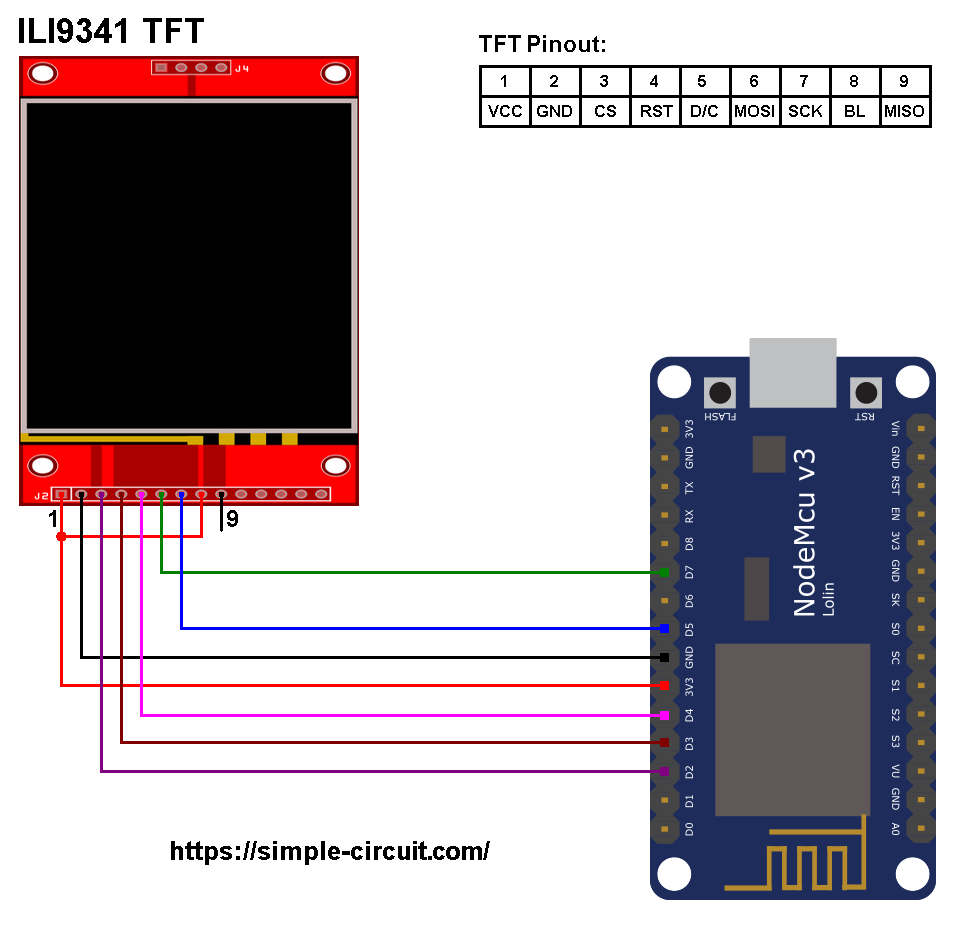
The ILI9341 TFT display is connected to the NodeMCU board as follows:
CS pin is connected to D2 (ESP8266EX GPIO4),
RST pin is connected to D3 (ESP8266EX GPIO0),
D/C pin is connected to D4 (ESP8266EX GPIO2),
MOSI pin is connected to D7 (ESP8266EX GPIO13),
SCK pin is connected to D5 (ESP8266EX GPIO14),
VCC and BL are connected to pin 3V3,
GND is connected to pin GND of the NodeMCU board.
Pins D5 (GPIO14) and D7 (GPIO13) are hardware SPI module pins of the ESP8266EX microcontroller respectively for SCK (serial clock) and MOSI (master-out slave-in).
Interfacing NodeMCU with ILI9341 TFT display code:
The Arduino code below requires two libraries from Adafruit Industries:
The first library is a driver for the ILI9341 TFT display which can be installed from Arduino IDE library manager (Sketch —> Include Library —> Manage Libraries …, in the search box write “ili9341” and choose the one from Adafruit).
The second library is Adafruit graphics library which can be installed also from Arduino IDE library manager.
The previous two libraries can also be installed manually:
Download both libraries from the following two links:
Adafruit ILI9341 TFT library —-> direct link
Adafruit graphics library —-> direct link
Go to Arduino IDE —> Sketch —> Include Library —> Add .ZIP Library … and browse for the .zip file (previously downloaded).
The same thing for the second file.
Hints:
The previous 2 libraries are included in the main code as shown below:
1 2 | #include <Adafruit_GFX.h> // include Adafruit graphics library #include <Adafruit_ILI9341.h> // include Adafruit ILI9341 TFT library |
The ILI9341 TFT display is connected to NodeMCU hardware SPI module pins (clock and data), the other pins which are: CS (chip select), RST (reset) and DC (data/command) are defined as shown below:
1 2 3 4 5 6 7 | #define TFT_CS D2 // TFT CS pin is connected to NodeMCU pin D2 #define TFT_RST D3 // TFT RST pin is connected to NodeMCU pin D3 #define TFT_DC D4 // TFT DC pin is connected to NodeMCU pin D4 // initialize ILI9341 TFT library with hardware SPI module // SCK (CLK) ---> NodeMCU pin D5 (GPIO14) // MOSI(DIN) ---> NodeMCU pin D7 (GPIO13) Adafruit_ILI9341 tft = Adafruit_ILI9341(TFT_CS, TFT_DC, TFT_RST); |
Full Arduino code:
The following Arduino code is from Adafruit ILI9341 library (graphicstest.ino) with some modifications in order to work with the above circuit diagram.
1 2 3 4 5 6 7 8 9 10 11 12 13 14 15 16 17 18 19 20 21 22 23 24 25 26 27 28 29 30 31 32 33 34 35 36 37 38 39 40 41 42 43 44 45 46 47 48 49 50 51 52 53 54 55 56 57 58 59 60 61 62 63 64 65 66 67 68 69 70 71 72 73 74 75 76 77 78 79 80 81 82 83 84 85 86 87 88 89 90 91 92 93 94 95 96 97 98 99 100 101 102 103 104 105 106 107 108 109 110 111 112 113 114 115 116 117 118 119 120 121 122 123 124 125 126 127 128 129 130 131 132 133 134 135 136 137 138 139 140 141 142 143 144 145 146 147 148 149 150 151 152 153 154 155 156 157 158 159 160 161 162 163 164 165 166 167 168 169 170 171 172 173 174 175 176 177 178 179 180 181 182 183 184 185 186 187 188 189 190 191 192 193 194 195 196 197 198 199 200 201 202 203 204 205 206 207 208 209 210 211 212 213 214 215 216 217 218 219 220 221 222 223 224 225 226 227 228 229 230 231 232 233 234 235 236 237 238 239 240 241 242 243 244 245 246 247 248 249 250 251 252 253 254 255 256 257 258 259 260 261 262 263 264 265 266 267 268 269 270 271 272 273 274 275 276 277 278 279 280 281 282 283 284 285 286 287 288 289 290 291 292 293 294 295 296 297 298 299 300 301 302 303 304 305 306 307 308 309 310 311 312 313 314 315 316 317 318 319 320 321 322 323 324 325 326 327 328 329 330 331 332 333 334 335 336 337 338 339 340 341 342 343 344 345 346 347 348 349 350 351 352 353 354 | /********************************************************************** Interfacing ESP8266 NodeMCU with ILI9341 TFT display (240x320 pixel). This is a free software with NO WARRANTY. http://simple-circuit.com/ /********************************************************************** /********************************************************************** This is our GFX example for the Adafruit ILI9341 Breakout and Shield ----> http://www.adafruit.com/products/1651 Check out the links above for our tutorials and wiring diagrams These displays use SPI to communicate, 4 or 5 pins are required to interface (RST is optional) Adafruit invests time and resources providing this open source code, please support Adafruit and open-source hardware by purchasing products from Adafruit! Written by Limor Fried/Ladyada for Adafruit Industries. MIT license, all text above must be included in any redistribution **********************************************************************/ #include <Adafruit_GFX.h> // include Adafruit graphics library #include <Adafruit_ILI9341.h> // include Adafruit ILI9341 TFT library #define TFT_CS D2 // TFT CS pin is connected to NodeMCU pin D2 #define TFT_RST D3 // TFT RST pin is connected to NodeMCU pin D3 #define TFT_DC D4 // TFT DC pin is connected to NodeMCU pin D4 // initialize ILI9341 TFT library with hardware SPI module // SCK (CLK) ---> NodeMCU pin D5 (GPIO14) // MOSI(DIN) ---> NodeMCU pin D7 (GPIO13) Adafruit_ILI9341 tft = Adafruit_ILI9341(TFT_CS, TFT_DC, TFT_RST); void setup() { Serial.begin(9600); Serial.println("ILI9341 Test!"); tft.begin(); // read diagnostics (optional but can help debug problems) uint8_t x = tft.readcommand8(ILI9341_RDMODE); Serial.print("Display Power Mode: 0x"); Serial.println(x, HEX); x = tft.readcommand8(ILI9341_RDMADCTL); Serial.print("MADCTL Mode: 0x"); Serial.println(x, HEX); x = tft.readcommand8(ILI9341_RDPIXFMT); Serial.print("Pixel Format: 0x"); Serial.println(x, HEX); x = tft.readcommand8(ILI9341_RDIMGFMT); Serial.print("Image Format: 0x"); Serial.println(x, HEX); x = tft.readcommand8(ILI9341_RDSELFDIAG); Serial.print("Self Diagnostic: 0x"); Serial.println(x, HEX); Serial.println(F("Benchmark Time (microseconds)")); Serial.print(F("Screen fill ")); Serial.println(testFillScreen()); delay(500); Serial.print(F("Text ")); Serial.println(testText()); delay(3000); Serial.print(F("Lines ")); Serial.println(testLines(ILI9341_CYAN)); delay(500); Serial.print(F("Horiz/Vert Lines ")); Serial.println(testFastLines(ILI9341_RED, ILI9341_BLUE)); delay(500); Serial.print(F("Rectangles (outline) ")); Serial.println(testRects(ILI9341_GREEN)); delay(500); Serial.print(F("Rectangles (filled) ")); Serial.println(testFilledRects(ILI9341_YELLOW, ILI9341_MAGENTA)); delay(500); Serial.print(F("Circles (filled) ")); Serial.println(testFilledCircles(10, ILI9341_MAGENTA)); Serial.print(F("Circles (outline) ")); Serial.println(testCircles(10, ILI9341_WHITE)); delay(500); Serial.print(F("Triangles (outline) ")); Serial.println(testTriangles()); delay(500); Serial.print(F("Triangles (filled) ")); Serial.println(testFilledTriangles()); delay(500); Serial.print(F("Rounded rects (outline) ")); Serial.println(testRoundRects()); delay(500); Serial.print(F("Rounded rects (filled) ")); Serial.println(testFilledRoundRects()); delay(500); Serial.println(F("Done!")); } void loop(void) { for(uint8_t rotation=0; rotation<4; rotation++) { tft.setRotation(rotation); testText(); delay(1000); } } unsigned long testFillScreen() { unsigned long start = micros(); tft.fillScreen(ILI9341_BLACK); tft.fillScreen(ILI9341_RED); tft.fillScreen(ILI9341_GREEN); tft.fillScreen(ILI9341_BLUE); tft.fillScreen(ILI9341_BLACK); return micros() - start; } unsigned long testText() { tft.fillScreen(ILI9341_BLACK); unsigned long start = micros(); tft.setCursor(0, 0); tft.setTextColor(ILI9341_WHITE); tft.setTextSize(1); tft.println("Hello World!"); tft.setTextColor(ILI9341_YELLOW); tft.setTextSize(2); tft.println(1234.56); tft.setTextColor(ILI9341_RED); tft.setTextSize(3); tft.println(0xDEADBEEF, HEX); tft.println(); tft.setTextColor(ILI9341_GREEN); tft.setTextSize(5); tft.println("Groop"); tft.setTextSize(2); tft.println("I implore thee,"); tft.setTextSize(1); tft.println("my foonting turlingdromes."); tft.println("And hooptiously drangle me"); tft.println("with crinkly bindlewurdles,"); tft.println("Or I will rend thee"); tft.println("in the gobberwarts"); tft.println("with my blurglecruncheon,"); tft.println("see if I don't!"); return micros() - start; } unsigned long testLines(uint16_t color) { unsigned long start, t; int x1, y1, x2, y2, w = tft.width(), h = tft.height(); tft.fillScreen(ILI9341_BLACK); x1 = y1 = 0; y2 = h - 1; start = micros(); for(x2=0; x2<w; x2+=6) tft.drawLine(x1, y1, x2, y2, color); x2 = w - 1; for(y2=0; y2<h; y2+=6) tft.drawLine(x1, y1, x2, y2, color); t = micros() - start; // fillScreen doesn't count against timing tft.fillScreen(ILI9341_BLACK); x1 = w - 1; y1 = 0; y2 = h - 1; start = micros(); for(x2=0; x2<w; x2+=6) tft.drawLine(x1, y1, x2, y2, color); x2 = 0; for(y2=0; y2<h; y2+=6) tft.drawLine(x1, y1, x2, y2, color); t += micros() - start; tft.fillScreen(ILI9341_BLACK); x1 = 0; y1 = h - 1; y2 = 0; start = micros(); for(x2=0; x2<w; x2+=6) tft.drawLine(x1, y1, x2, y2, color); x2 = w - 1; for(y2=0; y2<h; y2+=6) tft.drawLine(x1, y1, x2, y2, color); t += micros() - start; tft.fillScreen(ILI9341_BLACK); x1 = w - 1; y1 = h - 1; y2 = 0; start = micros(); for(x2=0; x2<w; x2+=6) tft.drawLine(x1, y1, x2, y2, color); x2 = 0; for(y2=0; y2<h; y2+=6) tft.drawLine(x1, y1, x2, y2, color); return micros() - start; } unsigned long testFastLines(uint16_t color1, uint16_t color2) { unsigned long start; int x, y, w = tft.width(), h = tft.height(); tft.fillScreen(ILI9341_BLACK); start = micros(); for(y=0; y<h; y+=5) tft.drawFastHLine(0, y, w, color1); for(x=0; x<w; x+=5) tft.drawFastVLine(x, 0, h, color2); return micros() - start; } unsigned long testRects(uint16_t color) { unsigned long start; int n, i, i2, cx = tft.width() / 2, cy = tft.height() / 2; tft.fillScreen(ILI9341_BLACK); n = min(tft.width(), tft.height()); start = micros(); for(i=2; i<n; i+=6) { i2 = i / 2; tft.drawRect(cx-i2, cy-i2, i, i, color); } return micros() - start; } unsigned long testFilledRects(uint16_t color1, uint16_t color2) { unsigned long start, t = 0; int n, i, i2, cx = tft.width() / 2 - 1, cy = tft.height() / 2 - 1; tft.fillScreen(ILI9341_BLACK); n = min(tft.width(), tft.height()); for(i=n; i>0; i-=6) { i2 = i / 2; start = micros(); tft.fillRect(cx-i2, cy-i2, i, i, color1); t += micros() - start; // Outlines are not included in timing results tft.drawRect(cx-i2, cy-i2, i, i, color2); } return t; } unsigned long testFilledCircles(uint8_t radius, uint16_t color) { unsigned long start; int x, y, w = tft.width(), h = tft.height(), r2 = radius * 2; tft.fillScreen(ILI9341_BLACK); start = micros(); for(x=radius; x<w; x+=r2) { for(y=radius; y<h; y+=r2) { tft.fillCircle(x, y, radius, color); } } return micros() - start; } unsigned long testCircles(uint8_t radius, uint16_t color) { unsigned long start; int x, y, r2 = radius * 2, w = tft.width() + radius, h = tft.height() + radius; // Screen is not cleared for this one -- this is // intentional and does not affect the reported time. start = micros(); for(x=0; x<w; x+=r2) { for(y=0; y<h; y+=r2) { tft.drawCircle(x, y, radius, color); } } return micros() - start; } unsigned long testTriangles() { unsigned long start; int n, i, cx = tft.width() / 2 - 1, cy = tft.height() / 2 - 1; tft.fillScreen(ILI9341_BLACK); n = min(cx, cy); start = micros(); for(i=0; i<n; i+=5) { tft.drawTriangle( cx , cy - i, // peak cx - i, cy + i, // bottom left cx + i, cy + i, // bottom right tft.color565(0, 0, i)); } return micros() - start; } unsigned long testFilledTriangles() { unsigned long start, t = 0; int i, cx = tft.width() / 2 - 1, cy = tft.height() / 2 - 1; tft.fillScreen(ILI9341_BLACK); start = micros(); for(i=min(cx,cy); i>10; i-=5) { start = micros(); tft.fillTriangle(cx, cy - i, cx - i, cy + i, cx + i, cy + i, tft.color565(0, i, i)); t += micros() - start; tft.drawTriangle(cx, cy - i, cx - i, cy + i, cx + i, cy + i, tft.color565(i, i, 0)); } return t; } unsigned long testRoundRects() { unsigned long start; int w, i, i2, cx = tft.width() / 2 - 1, cy = tft.height() / 2 - 1; tft.fillScreen(ILI9341_BLACK); w = min(tft.width(), tft.height()); start = micros(); for(i=0; i<w; i+=6) { i2 = i / 2; tft.drawRoundRect(cx-i2, cy-i2, i, i, i/8, tft.color565(i, 0, 0)); } return micros() - start; } unsigned long testFilledRoundRects() { unsigned long start; int i, i2, cx = tft.width() / 2 - 1, cy = tft.height() / 2 - 1; tft.fillScreen(ILI9341_BLACK); start = micros(); for(i=min(tft.width(), tft.height()); i>20; i-=6) { i2 = i / 2; tft.fillRoundRect(cx-i2, cy-i2, i, i, i/8, tft.color565(0, i, 0)); } return micros() - start; } |
The following video shows my simple hardware circuit test:
Discover more from Simple Circuit
Subscribe to get the latest posts sent to your email.

Thank you so much!
This will not compile for me testcircles not defined etc. Any help?
MEV
Can we use touch in it
I’m getting a white screen. I’m using an Arduino Nano. Any ideas how to fix this? I have tried changing the code to the suggestions above
I have the 128×160 Version of a similar display. In general it works but the Text is broken e.g. it it is mirrored and writing from right to left. Any ideas how to fix that?
Im am currently testing the code line by line and inspecting the output.
thanks
Erdie
Did you fix this? How?
Thank you. Works with no problem. Safed me a lot of time 🙂
White screen only 🙁
If in case, you still have the issue
Like Pete mentioned,
#define TFT_CS 4 // TFT CS pin is connected to NodeMCU pin D2 = GPIO 4
#define TFT_RST 0 // TFT RST pin is connected to NodeMCU pin D3 = GPIO 0
#define TFT_DC 2 // TFT DC pin is connected to NodeMCU pin D4 = GPIO 2
this should do the job
Have you tried this, it worked for me,
#define TFT_MOSI D7
#define TFT_SCLK D5
#define TFT_CS D2 // Chip select control pin
#define TFT_DC D4 // Data Command control pin
#define TFT_RST D3 // Reset pin (could connect to RST pin)
For some reason the pins on my ESP8266 12-E NodeMCU Kit weren’t defined as D2 D3 and D4 ; if you get an error on compile try replacing the define lines as such:
#define TFT_CS 4 // TFT CS pin is connected to NodeMCU pin D2 = GPIO 4
#define TFT_RST 0 // TFT RST pin is connected to NodeMCU pin D3 = GPIO 0
#define TFT_DC 2 // TFT DC pin is connected to NodeMCU pin D4 = GPIO 2
Thank you! This made it work for me. (Actually I’m using a different display and even a different display driver. I’m also using the LoLin NodeMCU module.) Regardless of all that, it’s working thanks to you.
LCD is only white, nothing happens
I changed setup to this and it worked
#define TFT_MOSI D7
#define TFT_SCLK D5
#define TFT_CS D2 // Chip select control pin
#define TFT_DC D4 // Data Command control pin
#define TFT_RST D3 // Reset pin (could connect to RST pin)
Thank you, very useful info!