This post shows how to control unipolar stepper motor using ESP8266 NodeMCU board (ESP-12E) and rotary encoder module.
The stepper motor used in this example is 28BYJ-48 (5V unipolar stepper motor) which usually comes with its driver board (equipped with ULN2003 integrated circuit).
In this project I used the rotary encoder shown below:
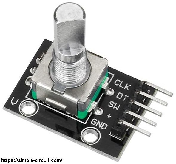
The rotary encoder module has 5 pins: GND, + (+5V or 3.3V), SW (push button), DT (pin B) and CLK (pin A).
As an addition to the rotary encoder there is a push button and three pull up resistors for pins SW, DT and CLK of 10k ohm. With the three pull-up resistors, the normal state of each terminal is logic high.
The rotary encoder generates (when rotating) two square waves on pins A (CLK) and B (DT) with 90° out of phase as shown in the figure below:
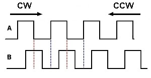
Since the normal state of pin A (CLK) and pin B (DT) are logic high we’ve to detect falling (transition from high to low) of one of them, here pin A is used to detect the movement of the rotary encoder in both directions (falling of pin A signal). Direction of rotation can be detected by knowing the status of pin B, if pin B is logic high this means the direction of rotation is clockwise (CW), and if pin B is logic low this means the direction of rotation is counter clockwise (CCW).
Hardware Required:
- ESP8266 NodeMCU board
- 28BYJ-48 stepper motor (with ULN2003A driver board)
- Rotary encoder module
- 5V power source
- Micro USB cable (for programming and powering the NodeMCU)
- Bread board
- Jumper wires
Stepper motor control with NodeMCU circuit:
Project circuit schematic diagram is shown below.
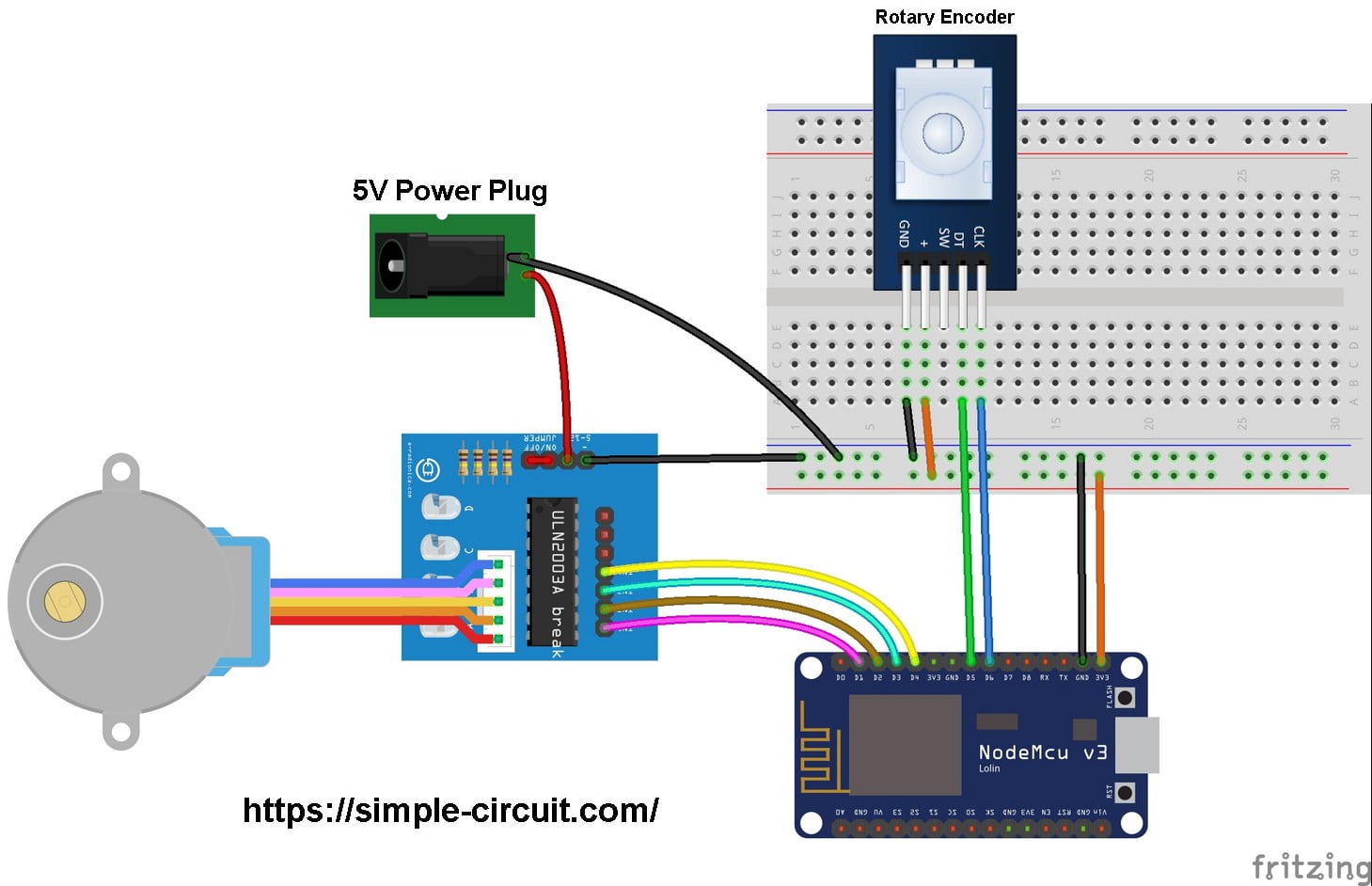
The stepper motor is connected to the ULN2003A board which is supplied with external power source of 5V. The control lines (IN1, IN2, IN3 and IN4) of this board are connected to the NodeMCU as:
IN1 to NodeMCU pin D1,
IN2 to NodeMCU pin D2,
IN3 to NodeMCU pin D3,
IN4 to NodeMCU pin D4.
The rotary encoder module has 5 pins: GND, + , SW, DT (pin B or data pin) and CLK (pin A or clock pin) where:
GND is connected to NodeMCU GND pin,
+ is connected to NodeMCU 3V3 pin,
SW is push button pin, not used in this example,
DT is connected to NodeMCU pin D5,
CLK is connected to NodeMCU pin D6.
Stepper motor control with NodeMCU code:
In this example I used Arduino stepper motor library (built-in) which simplifies the code, it’s included in the code using the following line:
1 | #include <Stepper.h> |
The stepper motor which I used in this project is 28BYJ-48, this motor is equipped with speed reducer of 1/64. The internal motor has 32 steps per one revolution which means the external shaft has 2048 steps per one revolution (64 x 32). Number of steps is defined in the code as shown below:
1 | #define STEPS 2048 |
and the connection of the control lines of the stepper motor with the NodeMCU board are defined as:
1 2 3 4 5 6 7 8 | // stepper motor control pins #define IN1 D1 // IN1 is connected to NodeMCU pin D1 (GPIO5) #define IN2 D2 // IN2 is connected to NodeMCU pin D2 (GPIO4) #define IN3 D3 // IN3 is connected to NodeMCU pin D3 (GPIO0) #define IN4 D4 // IN4 is connected to NodeMCU pin D4 (GPIO2) // initialize stepper library Stepper stepper(STEPS, IN4, IN2, IN3, IN1); |
The rotary encoder pin A (CLK) and pin B (DT) are connected to NodeMCU pins D6 and D5 respectively. They are defined as:
1 2 3 | // rotary encoder pins #define DT D5 // DT pin, connected to NodeMCU pin D5 (GPIO14) #define CLK D6 // CLK pin, connected to NodeMCU pin D5 (GPIO12) |
Both pins can be used to interrupt the NodeMCU microcontroller (ESP8266EX) whenever there is a change in the state of at least one pin. The following lines are used to enable interrupt-on-change for pins D6 and D5:
1 2 3 | // enable interrupts for rotary encoder pins attachInterrupt(DT, enc_read, CHANGE); attachInterrupt(CLK, enc_read, CHANGE); |
When the rotary encoder is rotated, it interrupts the NodeMCU microcontroller which directly will execute the function enc_read():
1 2 3 4 | void ICACHE_RAM_ATTR enc_read() { ... } |
Full Arduino code:
1 2 3 4 5 6 7 8 9 10 11 12 13 14 15 16 17 18 19 20 21 22 23 24 25 26 27 28 29 30 31 32 33 34 35 36 37 38 39 40 41 42 43 44 45 46 47 48 49 50 51 52 53 54 55 56 57 58 59 60 61 62 63 64 65 66 67 68 69 70 71 72 73 74 75 76 77 78 79 80 81 82 83 84 85 86 87 88 89 90 91 92 93 94 95 96 97 98 99 | /************************************************************************** * * ESP8266 NodeMCU stepper motor control with rotary encoder. * This is a free software with NO WARRANTY. * https://simple-circuit.com/ * *************************************************************************/ // include Arduino stepper motor library #include <Stepper.h> // number of steps per one revolution is 2048 ( = 4096 half steps) #define STEPS 2048 // stepper motor control pins #define IN1 D1 // IN1 is connected to NodeMCU pin D1 (GPIO5) #define IN2 D2 // IN2 is connected to NodeMCU pin D2 (GPIO4) #define IN3 D3 // IN3 is connected to NodeMCU pin D3 (GPIO0) #define IN4 D4 // IN4 is connected to NodeMCU pin D4 (GPIO2) // initialize stepper library Stepper stepper(STEPS, IN4, IN2, IN3, IN1); // rotary encoder pins #define DT D5 // DT pin, connected to NodeMCU pin D5 (GPIO14) #define CLK D6 // CLK pin, connected to NodeMCU pin D5 (GPIO12) int8_t quad = 0; uint8_t previous_data; void ICACHE_RAM_ATTR enc_read(); void setup(void) { pinMode(DT, INPUT); pinMode(CLK, INPUT); pinMode(IN1, OUTPUT); pinMode(IN2, OUTPUT); pinMode(IN3, OUTPUT); pinMode(IN4, OUTPUT); stepper.setSpeed(10); // set stepper motor speed to 10 rpm previous_data = digitalRead(DT) << 1 | digitalRead(CLK); // enable interrupts for rotary encoder pins attachInterrupt(DT, enc_read, CHANGE); attachInterrupt(CLK, enc_read, CHANGE); } void ICACHE_RAM_ATTR enc_read() { uint8_t current_data = digitalRead(DT) << 1 | digitalRead(CLK); if( current_data == previous_data ) return; if( bitRead(current_data, 0) == bitRead(previous_data, 1) ) quad -= 1; else quad += 1; previous_data = current_data; } int8_t encoder_update(void) { int8_t val = 0; while(quad >= 4){ val += 1; quad -= 4; } while(quad <= -4){ val -= 1; quad += 4; } return val; } // main loop void loop() { int8_t stp = encoder_update(); while(stp != 0) { int8_t dir = (stp > 0) ? -1 : 1; stepper.step( 20 * dir ); stp += dir; stp += encoder_update(); } digitalWrite(IN1, LOW); digitalWrite(IN2, LOW); digitalWrite(IN3, LOW); digitalWrite(IN4, LOW); delay(100); } // end of code. |
Stepper Motor Control with ESP8266 NodeMCU Video:
The following video shows my simple hardware circuit test of stepper motor control with ESP8266 NodeMCU board:
Discover more from Simple Circuit
Subscribe to get the latest posts sent to your email.

Works perfectly!
Great article! Have you figured out a way to ‘sleep’ this stepper motor in this configuration or any other? Thanks!